
Installation / Operation Instruction Manual


38
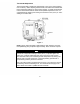
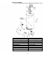
PARTS LIST DRAWING
(ACTUAL WATER HEATER VISUAL REPRESENTATION MAY VARY)
PART NAME AND DESCRIPTION
1. Blower Assembly 11. Inner Door (Left)
2. Pressure Switch (not shown) 12. Inner Door (Right)
3. Blower temp. switch (not shown) 13. Screw (Inner Door)
4. Flue Baffle or Flue Core 14. Outer Door
5. Flue Baffle Reducer 15. Screw (Outer Door)
6. Anode-Nipple 16. T & P Valve
7. Diptube-Nipple 17. Gas Feedline
8. Gas Valve 18. Gas Pilot
9. Resistive Device 19. Burner
10. Drain Valve 20. Gas Orifice