
Installation / Operation Instruction Manual

15
Venting continued-
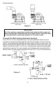
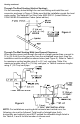
Through The Roof Venting (Vertical Venting):
Cut the necessary holes through the roof and ceiling and install the vent
connector as shown in Figure 4. Make sure that the installation meets the local
codes and/or The National Fuel Gas Code ANSI Z223.1 (Latest Edition) or
CGA/CAN B149 Installation Codes (latest edition).
Figure 4
Through The Wall Venting With Low Ground Clearance:
When venting cannot exit through the wall at a height greater than or equal to
12 in (30.5 cm) from the ground or from the anticipated snow level, then the
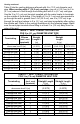
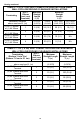
installation must be modified as shown below (see Figure 5). Refer to Table 4
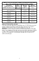
for maximum venting lengths using 2 in (5.1 cm) vent pipe, Table 5 for
maximum lengths using 3 in (7.6 cm) vent pipe, or Table 6 maximum lengths
using 4” (10.2 cm) vent pipe.
Figure 5
2” VENT INSTALLATION
3” VENT INSTALLATION
2” VENT INSTALLATION
3” VENT INSTALLATION
3” OR 4” VENT INSTALLATION
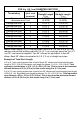
NOTE: For installations requiring both horizontal and vertical runs, the
following rule must be followed: Total length of straight pipe (both
horizontally and vertically) must NOT exceed the allowable length listed in
the Table 4, 5 and 6 for total number of elbows used.