
Installation / Operation Instruction Manual

14
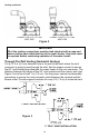
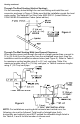
CONNECTION TO 2” (5.1 CM)
VENT PIPE
CONNECTION TO 3” (7.6 CM)
VENT PIPE
Venting continued-
Figure 2
Through The Wall Venting (Horizontal Venting):
Cut a 2 1/2 in (6.4 cm) diameter hole in the wall at the point where the vent
connector is going to pass through the wall. Use the proper cement to secure
the 90° vent terminal provided with the water heater to the vent connector. The
distance between the edges of the 90° vent terminal and the exterior wall (see
Figure 3) must be at least 1 in (2.5 cm). Use the proper cement and assembly
procedures to secure the vent connector joints between the terminal and the
blower outlet. Provide support brackets for every 5 ft (1.5 m) of horizontal vent.
Figure 3
IMPORTANT
All of the venting connections must be leak checked with a soap and
water solution upon initial start-up of the water heater. Any leaks must
be repaired before continuing operation of the water heater.
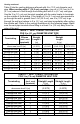
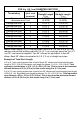
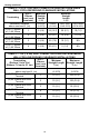
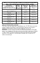
3” VENT INSTALLATION
2” VENT INSTALLATION
3” VENT INSTALLATION
2” VENT INSTALLATION
3” OR 4” VENT INSTALLATION