
Installation / Operation Instruction Manual
11
Venting System Condensation
Condensate formation does not occur in all installations of power vented water
heaters but should be protected against on installations where condensation can
form in the venting system.
Formation of condensation in the venting system of power vented water heaters is
dependent upon installation conditions including, but not limited to:
• ambient temperature and humidity of installation location,
• ambient temperature and humidity of venting space,
• vent distance and slope,
• and product usage.
In order to effectively control condensate from adversely affecting the mechanical
components of the water heater several methods may be employed:
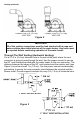
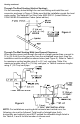
1. For horizontal installations the vent pipe can be installed with a downward
slope (not less than 1/8" (3 cm)) and away from the blower.
2. In order to prevent condensate from draining back into the blower (vertical
or horizontal runs), an optional condensate kit is available as a service part
(Condensate kit, p/n 239-45875-00). A molded exhaust adapter with drain
outlet is secured with one hose clamp, to the vent pipe. Tubing is provided
to drain any accumulated condensate away from the water heater and to a
suitable drain. The kit comes complete with instructions for proper
installation.
Venting Specifications for 40 Gallon (151.4 L) / 50 Gallon (189.2 L) /
60 Gallon (227.0 L):
This water heater is a power vented appliance and is designed to vent its
products of combustion through 2 in (5.1 cm), 3 in (7.6 cm) ), or 4 in (10.2 cm)
diameter vent pipe to the outdoors. The water heater may be either vented
horizontally through the wall or vertically through the roof. Use a 2” (5.1 cm) to
3” (7.6 cm) reducer to connect to the vent outlet when using 3” (7.6 cm) vent
pipe or 2” (5.1 cm) to 4” (10.2 cm) reducer to connect to the vent outlet when
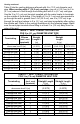
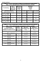
using 4” (10.2 cm) vent pipe. Apply proper cement at joint locations. Table 1
lists the maximum vent lengths for this water heater using 2 in (5.1 cm) vent
pipe. If possible, locate the water heater so that the venting length and number
of elbows are kept to the minimum distance necessary to reach the outside. If
the installation requires venting lengths that exceed the lengths listed for 2 in
(5.1 cm) vent pipe in Table 1 then use 3 in (7.6 cm) vent pipe for the vent
connector or 4” (10.2 cm) as necessary.
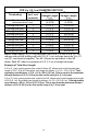
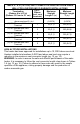
Table 2 lists the venting distances allowed with 3 in (7.6 cm) diameter vent
pipe. When venting with 3 in (7.6 cm) vent pipe, use a 3 in (7.6 cm) to 2 in
(5.1 cm) reducer to exit through the building wall with 2 in (5.1 cm) vent pipe.
Use the 2 in (5.1 cm) vent terminal supplied with the water heater to terminate
on the outside of the building. If the length of the 2 in (5.1 cm) needed to go
through the wall is greater than 14 in (35.6 cm), use 3 in (7.6 cm) vent pipe to
go through the wall and reduce to 2 in (5.1 cm) vent pipe immediately after
exiting the outside wall. Refer to the venting illustrations on the following pages.
Make sure the vent pipe terminal is at least 1 in (2.5 cm) away from the edge of
the wall.