
Installation / Operation Instruction Manual


13
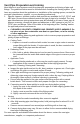
Venting continued-
Figure 2
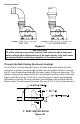
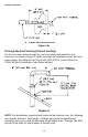
Through the Wall Venting (Horizontal Venting):
Cut a 3 1/2 in (8.9 cm) diameter hole in the wall at the point where the vent
connector is going to pass through the wall. Use the proper cement to secure
the 90° vent terminal provided with the water heater to the vent connector. The
distance between the edges of the 90° vent terminal and the exterior wall (see
Figure 3a & 3b) must be 1 in (2.5 cm). Use the proper cement and assembly
procedures to secure the vent connector joints between the terminal and the
blower outlet. Provide support brackets for every 5 ft (1.5 m) of horizontal vent.
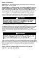
Figure 3a
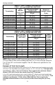
IMPORTANT
All of the venting connections must be leak checked with a soap and
water solution upon initial start-up of the water heater. Any leaks must
be repaired before continuing operation of the water heater.
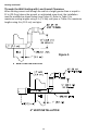
4” VENT INSTALLATION
3” VENT INSTALLATION
CONNECTION TO A 3” (7.6 CM) TO
4” (10.2 CM) REDUCER
CONNECTION TO 3” (7.6 CM)
VENT PIPE