PV Series Power Vent Gas Water Heaters SERVICE MANUAL Troubleshooting Guide and Instructions for Service (To be performed ONLY by qualified service providers) Models Covered by This Manual: Through‐The‐Wall Models: RG1PV40S*(N,X) RG1PV50S*(N,X) RG1PV55H*(N,X) RG2PV40T*(N,X) RG2PV50H*(N,X) RG2PV50T*(N,X) RG2PV75H*(N,X) LG1PV55H78*(N,X) LG2PV50H65*(N,X) LG2PV75H76*(N,X) (*) Denotes Warranty Years Manual 238‐51540‐00A 3/15 Save this manual for future reference
The Bradford White PV Series Power Vent GasGas Water Heaters Through-The-Wall Water Heaters Table of Contents 2 Page PV Service Procedure Introduction ................................................................................................................................ 4 --- How to Use This Manual .......................................................................................................... 5 --- Tools Required for Service ..............................................
PV Series WARNING: If the information in these instructions is not followed exactly, a fire or explosion may result causing property damage, personal injury, or death. DANGER Do not store or use gasoline or other flammable, combustible, or corrosive vapors and liquids in the vicinity of this or any other appliance. WHAT TO DO IF YOU SMELL GAS! x Do not try to light any appliance. x Do not touch any electrical switch; do not use any phone in your building.
PV Series Introduction The new Bradford White RG1PV & RG2PV water heaters are designed to provide reliable performance with enhanced standard features. New design features include reliable spark to pilot ignition system, enhanced diagnostics, simplified servicing, quiet operation, additional vent lengths, and Bradford White Defender Safety System® (not available on all models).
PV Series It is intended for this manual to be used by qualified service personnel for the primary purpose of troubleshooting and repair of the Bradford White PV Series water heaters. Understanding the sequence of operation section of this manual will contribute greatly to troubleshooting the water heater. The Honeywell WV4462A Electronic Gas Control will display error codes in the event of abnormal operation. Error codes are listed in the troubleshooting chart beginning on page 15 of this service manual.
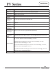
PV Series Power supply Gas Supply Pipe Approved Gas Type Gas Pressure Venting System Approved Vent Materials Minimum Clearance for Servicing Water Supply Pressure Gas Control ECO Limit Residential Temperature Set Point Range Commercial Temperature Set Point Range Blower Temperature Switch Dedicated 115 VAC, 60 Hz, 15A. Minimum 1/2” NPT (schedule 40 black iron pipe recommended). Natural Gas or Propane, unit must match gas type supplied. 5.0” W.C. min. for Natural Gas, 11.0” W.C. min. for Propane, 14.
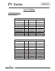
PV Series Vent Tables Venting Specifications for: RG1PV40S, RG2PV40T RG1PV50S, RG2PV50T 2" Diameter (5.1 cm) Vent Connector Lengths # of Maximum Straight Minimum Straight Terminating Elbows Length ft. (m) Length ft. (m) Through the Wall 1 45 (16.8) 2 (.6) Through the Wall 2 40 (15.2) 2 (.6) Through the Wall 3 35 (13.7) 2 (.6) Through the Wall 4 30 (12.2) 2 (.6) Through the Roof Through the Roof Through the Roof Through the Roof Through the Roof 0 1 2 3 4 50 (18.3) 45 (16.8) 40 (15.
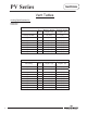
PV Series Vent Tables Venting Specifications for: RG2PV50H LG2PV50H 3" Diameter (7.6 cm) Vent Connector Lengths # of Maximum Straight Minimum Straight Terminating Elbows Length ft. (m) Length ft. (m) Through the Wall 1 55 (16.8) 2 (.6) Through the Wall 2 50 (15.2) 2 (.6) Through the Wall 3 45 (13.7) 2 (.6) Through the Wall 4 40 (12.2) 2 (.6) Through the Roof Through the Roof Through the Roof Through the Roof 0 1 2 3 60 (18.3) 55 (16.8) 50 (15.2) 45 (13.7) 7 (2.1) 7 (2.1) 7 (2.1) 7 (2.
PV Series Vent Tables Venting Specifications for: RG1PV55H RG2PV75H LG1PV55H LG2PV75H 3" Diameter (7.6 cm) Vent Connector Lengths # of Maximum Straight Minimum Straight Terminating Elbows Length ft. (m) Length ft. (m) Through the Wall 1 45 (13.7) 2 (.6) Through the Wall 2 40 (12.2) 2 (.6) Through the Wall 3 35 (10.7) 2 (.6) Through the Wall 4 30 (9.1) 2 (.6) Through the Roof Through the Roof Through the Roof Through the Roof 0 1 2 3 50 (15.2) 45 (13.7) 40 (12.2) 35 (10.7) 7 (2.1) 7 (2.
PV Series Control Timings Ignition State Pre-purge Trial for Ignition Flame Stabilization Period Inter-purge Flame Failure Response Time Post-purge PS Fault Delay (failed open/close) Soft Lockout ECO Limit Lockout Verify Resistive Delay Flammable Vapor Sensor/Simulated Resistive Load Lockout Hardware Error Lockout 10 10 Timing 2 Seconds 90 Seconds 3 Seconds 15 Seconds 1.5 Seconds (2 second maximum; 1 second minimum.
PV Series Power Up Sequence 1. Start Up. Upon power up, the control runs a safe-start check with a typical start-up delay of 5 seconds. 2. Flammable Vapor. To assure no outputs are energized if the “Flammable Vapor Sensor” (for RG1PV40S, RG1PV50S, RG2PV40T, RG2PV50T, RG2PV50H) or “Simulated Resistive Device” (for RG1PV55H and RG2PV75H) is out of range, the control will test the “Flammable Vapor Sensor” or “Simulated Resistive Device” for proper operating range.
PV Series Normal Heating Sequence (cont.) 7. Steady state operation. During steady state operation, the control monitors: Thermostat temperature sensor-when set point temperature is satisfied, gas valve is shut down and blower will post purge for 15 seconds. Control LED flashes a short flash once every 4 seconds (idle) status code. Pressure switch / blower temperature switch-if either switch opens, the pilot valve and the main valve are both shut down.
PV Series Abnormal Operation (cont.) times, then 3 times twice with 3 second pauses. The error self clears if the fault clears for at least 15 seconds. c. Water temperature in excess of ECO (energy cut out) limit -The gas control immediately turns off pilot & main valves and proceeds to flash 4 times with 3 second pause. Blower continues to run until gas control is reset.
PV Series Abnormal Operation (cont.) 5. Flame sensing fault: a. Flame lost during run-the gas control turns off pilot and main valves, runs blower for 15 seconds (inter-purge). The gas control increments the recycle count, if the recycle count has not reached its limit (4), another trial for ignition begins. If the recycle count has been reached, the gas control turns off the blower and flashes 6 times then, 3 times with 3 second pause. The gas control waits 5 minutes before repeating the ignition sequence.
PV Series Observe green LED indicator on electronic gas control. Error flash codes are displayed with a three second pause before repeating. Check and repair the system as noted in the troubleshooting table below.
PV Series LED Status Probable Cause Six-one flash, three second pause Failed to light pilot. System auto resets. 1. Unstable pilot. 2. Pilot tube blocked or restricted. 3. Oxidation build up on pilot electrode. 4. Wire damage to pilot assembly or bad connection at gas valve. Six-two flash, three second pause Pressure switch or blower temp switch opened during burner operation. System auto resets. 1. Vent blockage or improper vent configuration. 2. Pressure switch tubing kinked or blocked. 3.
PV Series Burner Inspection At periodic intervals (every 6 months) a visual inspection should be made of the pilot and main burner for proper operation and to assure no debris is accumulating. Pilot flame should be stable, some causes for an unstable pilot flame are: a) Water heater vent is less than the allowable vent length. b) Gas pressure is out of specification. c) Pilot flame not fully engulfing spark/flame sensor.
PV Series Burner Cleaning Step 1. Step 2. Step 3. Step 4. Step 5. Step 6. Step 7. Step 8. Position gas control power switch to the “OFF” position and unplug heater from wall outlet. Turn off gas supply to water heater. Remove outer jacket door and inner door per service procedure XIII on page 39. Disconnect pilot tube (7/16” wrench) and feedline (3/4” wrench) from gas control. Disconnect igniter/flame sensor wire from gas control. Remove burner assembly from combustion chamber.
PV Series Pilot Inspection, Testing and Replacement Step 1. Position gas control power switch to the “OFF” position and unplug heater from wall outlet. Step 2. Turn off gas supply to water heater. Step 3. Remove outer jacket door and inner door per service procedure XIII on page 39. Step 4. Disconnect pilot tubing nut (7/16” wrench) and feedline nut (3/4” wrench) from gas control. Step 5. Disconnect igniter/flame sense wire from gas control. Step 6. Remove burner assembly from combustion chamber. Step 7.
PV Series Step 15. To resume operation, follow the instructions located on the lighting instruction label or the lighting instructions located in the installation and operation manual. Pressure Switch Testing Step 1. Step 2. Step 3. 20 20 WARNING 115 volt potential exposure. Use caution to avoid personal injury. Position power switch on gas control to the “OFF” position. Remove the three screws (Phillips screw driver) from control access cover on blower assembly and remove cover (see photo 1).
PV Series Pressure Switch Replacement WARNING Position gas control power 115 volt potential exposure. Use switch to “OFF” position. caution to avoid personal injury. Step 2. Remove the three screws (Phillip’s screw driver) from control access cover on blower assembly and remove cover (see photo 3). Step 3. Carefully remove pressure switch from blower housing (see photo 4). Step 4. Disconnect tubing from pressure switch. (see photo 5). Step 5. Disconnect yellow wires from pressure switch (see photo 6).
PV Series Blower Testing Step 1. Step 2. 22 22 WARNING 115 volt potential exposure. Use Position gas control caution to avoid personal injury. power switch to “ON” position and adjust control to call for heat. Remove the three screws (Phillip’s screw driver) from control access cover on blower assembly and remove cover (see photo 7).
PV Series Blower Removal Step 1. Position gas control power switch to “OFF” position and adjust control to call for heat. Step 2. Unplug blower power cord from wall outlet. Step 3. Disconnect vent system from exhaust adapter on top of blower. Step 4. Remove exhaust adapter from blower (blade screw driver) and retain for use on new blower. Step 5. Unplug cord sets from blower. Step 6. Remove the three blower mounting screws (1/4” nut driver). Step 7. Remove blower with gasket from water heater.
PV Series Blower Temperature Switch Testing Position power switch on gas control to the “OFF” position. Step 1. Step 2. 24 24 Remove the three screws (Phillip’s screw driver) from control access cover on blower and remove cover (see photo 14). Locate blower temperature switch (see photo 15). WARNING 115 volt potential exposure. Use caution to avoid personal injury.
PV Series Blower Temperature Switch Replacement WARNING 115 volt potential exposure. Use caution to avoid personal injury. Step 1. Position gas control power switch to the “OFF” position and unplug heater from wall outlet. Step 2. Remove the three screws (Phillip’s screw driver) from the control access cover on blower and remove cover (see photo 16). Step 3. Locate blower temperature switch (see photo 17). Step 4. Disconnect red and yellow wire leads from switch. Step 5.
PV Series Line Pressure The gas control is designed for a maximum line pressure of 14.0” W.C. and a minimum line pressure of 1.0” W.C. over the water heater’s rated manifold pressure (check rating plate). Line pressure must be checked with the main burner on and off to assure proper readings. Manifold Pressure Testing (this procedure presumes a maximum line pressure of 14.0” W.C.) Step 1. Set the Gas Control to the “OFF” position. Step 2.
PV Series ECO (Energy Cut Out) The Honeywell gas control is designed with an ECO device that will reset. To reset the gas control after an error code (4), turn the gas control knob to the “LOW” position and wait a minimum of (5) minutes before relighting following the instructions located on the lighting instruction label or the lighting instructions located in the installation and operation manual. Gas Control Disassembly/Reassembly Step 1. Set the gas control to the “OFF” position. Step 2.
PV Series Gas Control Disassembly/Reassembly (cont.) Step 8. Disconnect temperature sensor from control board. Step 9. To reassemble gas control, follow the previous steps in reverse order. Once gas control is reassembled, burner assembly is reinstalled, and the gas supply line is reconnected, resume water supply to water heater. Be sure tank is full of water before relighting. Step 10.
PV Series Temperature Sensor Testing Using a multi-meter set to the ohms setting, insert one meter probe (see caution) into center wire position of temperature sensor connector, insert the second probe (see caution) into either of the outside wire positions (see photo 19). Alternate the probe on the outside position to the opposite outside wire position (see photo 20). CAUTION Do not use standard multi-meter probes for this test. Doing so will damage connector.
PV Series Determine Water Temperature Inside Tank WARNING Stored water may be HOT WHEN PERFORMING THE FOLLOWING STEPS IN THIS PROCEDURE. Take necessary precaution to prevent personal injury. Note: It is important to understand once the resistance for the temperature sensor is determined from page 29, water flow through the heater should not occur. Prior to performing the steps below, turn off the cold water supply to the water heater.
PV Series Gas Control Removal From Water Heater Step 1. Position the gas control power switch to the “OFF” position and unplug heater from wall outlet. Step 2. Drain the heater to a point below the gas control level. Step 3. Turn off the gas supply to the water heater and disconnect gas piping from the gas control. Step 4. Disconnect wire harnesses from the gas control. Step 5. Remove the outer jacket burner access door. Step 6. Right side inner door removal. a.
PV Series Reinstallation of inner door assembly. c. Prior to reinstallation of inner door, fully inspect for the following: -Tears -Other imperfections that will inhibit proper seal -Missing material -Gasket adhesion to inner door -Cracks -Material left on combustion chamber (around opening) -Dirt or debris If the gasket is not affected by any of the above, gasket replacement may not be required. If replacement is required, replace using new gasket kit following the instructions provided with d.
PV Series Flammable Vapor/Simulative Resistance Device Testing Step 1. Position power switch on gas control to the “OFF” position. Step 2. Disconnect flammable vapor sensor from gas control. Step 3. Using a multi-meter set to the ohms setting, check resistance of flammable vapor sensor. Resistance must be between 3,000 ohms and 48,000 ohms. If outside of this range replace Flammable Vapor Sensor or Simulated Resistive Device. CAUTION DO NOT use a standard multi-meter probe for this test.
PV Series Safety Circuit Voltage Trace NOTE: This procedure assumes a cool tank. Remove three screws (Phillips Screw driver) from control access cover on blower and remove cover (see photo 19). 34 34 WARNING 115 volt potential exposure. Use caution to avoid personal injury.
PV Series 115 VAC Circuit Trace Step 1. Step 2. Verify 115 VAC and proper polarity at wall outlet. With unit plugged in and control power switch in the “ON” position verify LED status. WARNING 115 volt potential exposure. Use caution to avoid personal injury.
PV Series Diptube Inspection & Replacement Step 1. Step 2. Step 3. Step 4. Step 5. Step 6. Step 7. 36 36 WARNING Water Heater components and stored water may be HOT when performing the following steps in this procedure. Take necessary precaution to prevent personal injury. Position on/off switch of gas control valve to “OFF” position and unplug water heater from wall outlet. Turn off cold water supply to water heater.
PV Series Anode Inspection & Replacement WARNING Water Heater components and stored water may be HOT when performing the following steps in this procedure. Take necessary precaution to prevent personal injury. Step 1. Step 2. Step 3. Step 4. Step 5. Step 6. Step 7. Position on/off switch of gas control valve to the “OFF” position and unplug water heater from wall outlet. Turn off cold water supply to water heater. Connect hose to drain valve of water heater and route to an open drain.
PV Series Flue Baffle Inspection and Replacement Step 1. Step 2. Step 3. Step 4. Step 5. Step 6. Step 7. Step 8. Step 9. Step 10. Step 11. 38 38 Position gas control power switch to the “OFF” position and unplug blower from wall outlet. Disconnect vent system from exhaust adapter on top of blower. Unplug cord sets from blower (see photo 26). Remove the three blower mounting screws (1/4” nut driver) (see photo 26). Remove blower with gasket from water heater.
PV Series Inner Door Removal Procedure Step 1. Position gas control power switch to the “OFF” position. Step 2. Remove outer jacket burner access door. Step 3. Inner Door removal. a. Remove (2) ¼” hex drive screws from right side inner door. b. Remove (2) ¼” drive screws from flange section of inner door. c. Remove (2) ¼” drive screws from left side inner door. d. Remove inner door and inspect per step 4. Step 4.
PV Series Installation of Inner Door With Gasket Step 7. Step 8. Step 9. 40 40 Clean any residual gasket residue or other debris from combustion chamber surface before installing the inner door/gasket assembly. Place the left side inner door into position first. Firmly position the radiused channel of the inner door around the feedline. Using the ¼” hex drive screws from step 3c, secure left side inner door in place.
PV Series Installation of Inner Door With Gasket (cont.) Step 10. Firmly place right side inner door flange against the left side inner door flange and secure with (2) ¼” hex drive screws from step 3b. DO NOT OVER TIGHTEN SCREWS. Step 11. Align right side inner door to combustion chamber and verify the fastener holes of the combustion chamber are aligned with right side inner door slotted opening. Verify seal integrity around combustion opening.
PV Series ScreenLok® Flame Arrestor Cleaning Step 1. Step 2. Step 3. Step 4. Step 5. Step 6. Step 7. Step 8. Step 9. 42 42 NOTICE Some models are not equipped with the ScreenLok® Flame Arrestor. Position Gas Control power switch to the “OFF” position. Remove outer door. Remove outer jacket door and inner door per service procedure XIII on page 39.
PV Series Frozen Exhaust Vent Terminal If an exhaust vent terminal is blocked with ice or snow due to severe conditions, the pressure switch and control will not allow the burner to operate. This will result in a three flash error code. Once the blockage is removed (through melting or other means) the controls will let the burner operate. The position of the vent terminals in relation to each other and terminals from other appliances can have an effect on the potential for blockage due to ice or snow.
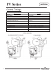
PV Series 1. 2. 3. 4. 5. 6. 7. 8. 9. 44 Blower Complete Air Mixing Inlet Cover Pressure Switch Blower Temp. Switch Blower Gasket Blower Power Cord Vent Adapter Kit Condensate Hose Kit Flue Reducer (“H” Models only) 44 10. Heat Trap Outlet 11. Hot Water Outlet Anode 12. Flue Baffle 13. Heat Trap Inlet 14. Inlet Dip Tube 15. Wire Harness 16. T&P Valve 17. ¾ NPT Plug (“H” Models only) 18. Burner Assy. 19. Main Burner 20.