GAS WATER HEATER A Spanish language version of these instructions is available by contacting the company listed on the rating plate. La versión espãnola de estas instrucciones se puede obtener al escribirle a la fábrica cuyo nombre aparece en la placa de especificaciones.
CONGRATULATIONS! You have just purchased one of the finest water heaters on the market today! This installation, operation and instruction manual will explain in detail the installation and maintenance of your new Mobile Home Water Heater. We strongly recommend that you contact a plumbing professional for the installation of this water heater. We require that you carefully read this manual, as well as the enclosed warranty, and refer to it when questions arise.
For Canadian Installations TABLE OF CONTENTS Page GENERAL INFORMATION ............................................................................. 4 INSTALLATION ............................................................................................... 5 Locating the Water Heater........................................................................ 5 Minimum Clearances ................................................................................ 8 Drain Pan Installation .........................
GENERAL INFORMATION This water heater must be installed in accordance with The Federal Manufactured Home Construction and Safety Standard (H.U.D. Title 24, Part 3280.707d2) or CAN/CSA Z240 MH series, mobile home. In the absence of such a standard, the water heater should be installed in accordance with the Standard for Mobile Homes (ANSI/NFPA NO. 501-B1977).
General Information continued- IMPORTANT Before proceeding, please inspect the water heater and components for possible damage. DO NOT install any damaged components. If damage is evident then please contact the supplier where the water heater was purchased, or the manufacturer listed on the rating plate for replacement parts. This water heater has been manufactured for operation at altitudes from sea level to 2000 feet (610m) (unless otherwise specified on the water heater).
Installation (Locating The Water Heater) continued- WARNING Water heaters are heat producing appliances. To avoid damage or injury there must be no materials stored against the water heater or vent-air intake system and proper care must be taken to avoid unnecessary contact (especially by children) with the water heater and vent-air intake components.
Installation (Locating The Water Heater) continued- WARNING Liquefied petroleum gases/propane gases are heavier than air and will remain at floor level if there is a leak. Basements, crawl spaces, closets and areas below ground level will serve as pockets for accumulation of leaking gas. Before lighting, smell all around the appliance area for gas. Be sure to smell next to the floor. IF YOU SMELL GAS: • Do not try to light any appliance.
Minimum Clearances WARNING Failure to adhere to these installation and operating instructions may create a hazard to life and property and will nullify the warranty. This installation must allow access to the front of the water heater and adequate clearance must be provided for servicing and operating this water heater. The water heater may be installed on either a combustible or noncombustible floor.
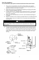
Drain Pan Installation for non-flammable vapor ignition resistant manufactured home water heaters 1. 2. 3. 4. 5. This section is intended for use with non-flammable vapor ignition resistant manufactured home water heaters that will be installed in an application where a drain pan is required. After hole is cut in floor and underside sheathing, and before the water heater is installed, prepare drain pan. Locate and cut a 3-1/2” diameter hole in drain pan at 4-1/2” from center (see Figure 2).
Combustion Air Supply All combustion air must be supplied from outdoors by one of the following installation methods and as illustrated in Figure 5. The flow of combustion and ventilating air must not be obstructed. Adequate air must be supplied for combustion and ventilation. An insufficient supply of air will cause recirculation of combustion products resulting in air contamination that may be hazardous to life.
Venting WARNING The vent system must be installed properly. Failure to properly install the vent system could result in property damage, personal injury, or death. Make certain the flue baffle is in place and centered in the flue tube. Cut a 7 1/4 inch (18.5cm) diameter hole in the ceiling and roof directly above the flue of the water heater. Center the water heater beneath the 7 1/4 inch (18.5cm) diameter hole in the roof and ceiling for proper alignment of the flue tube and roof jack vent.
Water Connections NOTE: BEFORE PROCEEDING WITH THE INSTALLATION, CLOSE THE MAIN WATER SUPPLY VALVE. After shutting off the main water supply, open a faucet to relieve the water line pressure to prevent any water from leaking out of the pipes while making the water connections to the water heater. After the pressure has been relieved, close the faucet. The COLD water inlet and HOT water outlet are identified on the top of the water heater.
Installation (Water connections) continued- WARNING For protection against excessive temperatures and pressure, install temperature and pressure protective equipment required by local codes, but not less than a combination temperature and pressure relief valve certified by a nationally recognized testing laboratory that maintains periodic inspection of production of listed equipment or materials as meeting the requirements of the Standard for Relief Valves and Automatic Gas Shutoff Devices for Hot Water Su
Installation (Water connections) continued- WARNING Hydrogen gas can be produced in an operating water heater that has not had water drawn from the tank for a long period of time (generally two weeks or more). Hydrogen gas is extremely flammable. To prevent the possibility of injury under these conditions, we recommend the hot water faucet to be open for several minutes at the kitchen sink before you use any electrical appliance, which is connected to the hot water system.
Gas Connections The gas supply lines must meet all requirements of the National Fuel Gas Code (ANSI Z223.1-Latest Edition), or in Canada CAN/CGA B149.1 Natural Gas Installation Code (Latest Edition) or CAN/CGA B149.2 Propane Installation Code (Latest Edition). The minimum permissible gas supply pressure for the purpose of input adjustment is one (1.0) inch (0.25 kPa) water column above the operating manifold pressure. See the rating plate and gas valve for the manifold pressure and gas type.
Gas Conversion Instructions Unless specifically ordered for operation on natural gas, this water heater is normally equipped for operation on liquefied petroleum (LP) gas but may be converted by following these gas conversion instructions. Caution: Make sure gas to be supplied to this water heater following the conversion matches the gas being converted to. CAUTION All gas conversions must be performed by qualified service personnel only.
Gas Conversion Instructions continued- 7. Replace the burner assembly, reconnect all fittings and check for leaks. Refer to “Gas Connections”. 8. Close and/or replace inner and outer doors. 9. To light pilot, follow the lighting instructions provided on the water heater and in this installation and operation instruction manual. 10. Remove “equipped for” card from cloth bag and attach to gas piping as close to gas control as possible.
Gas Conversion Instructions continued- 7. Replace the burner assembly and reconnect all fittings and check for leaks. Refer to “Gas Connections”. 8. Close and/or replace inner and outer doors. Note: For closed combustion product, make sure screws are tight and seal is made around gas supply tube to burner. 9. To light pilot, follow the lighting instructions provided on the water heater and in this installation and operation instruction manual. 10.
Gas Conversion Instructions continued- Figure 8 4. Replace the plastic cover. 5. Disconnect thermocouple, gas supply tube and pilot tube from the gas valve and remove the burner assembly from the water heater. 6. Remove the “RED” color coded L.P. orifice and pilot assembly and replace with natural gas orifice and pilot assembly provided in the cloth bag attached to the water heater. 7. Replace the burner assembly, reconnect all fittings and check for leaks. Refer to “Gas Connections”. 8.
GENERAL OPERATION WARNING Water heaters are heat producing appliances. To avoid damage or injury there must be no materials stored against the water heater or vent-air intake system, and proper care must be taken to avoid unnecessary contact (especially by children) with the water heater and vent-air intake system.
Lighting and Shutdown Instructions 21
Thermostat Adjustment Figure 9 The thermostat dial is set to its lowest temperature setting when shipped from the factory. Remember that lower temperature settings are more energy efficient. Adjust the temperature by turning the thermostat dial. It is suggested that the starting point setting not be greater than the ” “ mark on the thermostat dial (approximately 120°F [48.9°C]) as pictured above. Rotate the thermostat dial clockwise to decrease the temperature setting.
Thermostat Adjustment Continued- Figure 11 The thermostat dial is set to its lowest temperature setting when shipped from the factory. Remember that lower temperature settings are more energy efficient. Adjust the temperature by turning the thermostat dial. It is suggested that the starting point setting not be greater than the ” “ mark on the thermostat dial (approximately 120°F [48.9°C]) as pictured above. Rotate the thermostat dial clockwise to decrease the temperature setting.
General Operation continued- DANGER Hotter water increases the risk of scald injury. Scalding may occur within five (5) seconds at a temperature setting of 140°F (60°C). To protect against hot water injury, install an ASSE approved mixing valve in the water system. This valve will reduce point of discharge temperature by mixing cold and hot water in branch water lines. A licensed plumbing professional or local plumbing authority should be consulted.
MAINTENANCE IMPORTANT The water heater should be inspected at a minimum annually by a qualified service technician for damaged components and/or joints not sealed. DO NOT operate this water heater if any part is found damaged or if any joint is found not sealed. The following maintenance should be performed by a qualified service technician at the minimum periodic intervals suggested below.
Maintenance Continued- 6. At least once a year, check the combination temperature and pressure relief valve to insure that the valve has not become encrusted with lime. Lift the lever at the lever at the top of the valve several times until the valve seats properly without leaking and operates freely. WARNING THIS WATER MAY BE HOT . 7. Monthly drain off a gallon of water to remove silt and sediment. 8.
READ THE WARRANTY FOR A FULL EXPLANATION OF THE LENGTH OF TIME THAT PARTS AND THE WATER HEATER ARE WARRANTED.
TYPICAL INSTALLATION 28
PARTS LIST GAS FIRED MANUFACTURED HOME (MOBILE HOME) PART NAME AND DESCRIPTION 1. Gas Conversion Kit 12. Inner Door 2. Jacket Top 3. Fiberglass Insulation 13. Convertible gas control valve 14. Pilot Assembly 4. Glass Lined Tank 15. Gas Feed Line (Burner) 5. Tank Skirt Assembly 16. Main Burner Orifice 6. Jacket Base Assembly 17. Burner 7. Flue Baffle Assembly 18. Pilot Orifice (Not Shown) 8. Cold Water Inlet Tube w/Nipple 19. Outer Door 9. Magnesium Anode 20. Radiation Shield 10.
NOTES 30
NOTES 31
NOTES 32