
Install Instructions
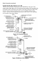
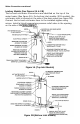
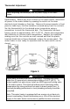
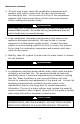
Table Of Contents

14
Water Connections continued-
Utility Models (See Figure 3)
All utility models are supplied with inlet and outlet nipples located in a plastic
bag attached to the w ater heater. The hot and cold w ater locations are
identified on the side of the water heater. Apply appropriate amount of
thread sealant to the provided nipples and install nipples into the side of the
tank. For 20 gallon utility models, install the supplied anode/nipple
combination at the HOT outlet location. Connect the hot and cold water lines
to the nipples using unions. Install a listed temperature-pressure relief valve
in the opening on the side of the water heater. Install a vacuum relief anti-
siphon device in the cold water inlet line when using side cold water
connection.
The 6 and 12 gallon models are equipped for installation w ith either side or
top water connections. They are shipped from the factory with the alternate
top connections plugged. The alternate top inlet is supplied w ith a dip tube. If
the top water connections are needed, remove pipe plugs from the alternate
top connections, apply appropriate amount of thread sealant to the provided
nipples and install nipples in desired top location. Apply appropriate amount
of thread sealant to the pipe plugs and install pipe plugs in the side locations.
Install a vacuum relief anti-siphon device in the cold water inlet line when
using side cold water connection.
Figure 3