Residential & Light Duty Commercial Power Direct Vent Models SERVICE MANUAL Troubleshooting Guide and Instructions for Service (To be performed ONLY by qualified service providers) Models Covered by This Manual: RC2PDV50H*(N,X) LC2PDV50H76*(N,X) (*) Denotes Warranty Years Manual 238-53795-00A REV 11/19 Save this manual for future reference
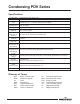
The Bradford White Condensing PDV Series Through-The-Wall Gas Water Heaters Table of Contents Page Introduction...................................................................................................................4 --- How to Use This Manual ............................................................................................5 --- Tools Required for Service .........................................................................................5 --- Specifications ...............
Condensing PDV Series WARNING: If the information in these instructions is not followed exactly, a fire or explosion may result causing property damage, personal injury, or death. FOR YOUR SAFETY Do not store or use gasoline or other flammable, combustible, or corrosive vapors and liquids in the vicinity of this or any other appliance. WHAT TO DO IF YOU SMELL GAS: x DO NOT try to light any appliance. x DO NOT touch any electrical switch; do not use any phone in your building.
Condensing PDV Series Introduction The Bradford White residential condensing water heaters are designed to provide reliable performance with enhanced standard features. New design features include reliable spark to pilot ignition system, enhanced diagnostics, simplified servicing, significantly quiet operation and additional vent lengths.
Condensing PDV Series How to Use This Manual It is intended for this manual to be used by qualified service personnel for the primary purpose of troubleshooting and repair of the Bradford White Condensing PV Series water heaters. Understanding the sequence of operation section of this manual will contribute greatly to troubleshooting the water heater. The Honeywell WV4462A Electronic Gas Control will display error codes in the event of abnormal operation.
Condensing PDV Series Specifications Power Supply Gas Supply Pipe Approved Gas Type Gas Pressure Venting System Approved Vent Materials Minimum Clearance for Servicing Water Supply Pressure Gas Control ECO Limit Residential Temperature Set Point Range Commercial Temperature Set Point Range Blower Temperature Switch Dedicated 115 VAC, 60 Hz, 15A Minimum 1/2” NPT (schedule 40 black iron pipe recommended) Natural Gas or L.P., unit must match gas type supplied 5.0” w.c. min. for Natural Gas, 11.0” w.c. min.
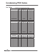
Condensing PDV Series Vent Tables 2" Diameter (5.1 cm) Vent Connector Lengths # of Maximum Straight Minimum Straight Terminating Elbows Length ft. (m) Length ft. (m) Through the Wall Through the Wall Through the Wall Through the Wall 1 2 3 4 45 (13.7) 40 (12.2) 35 (10.7) 30 (9.2) 2 (.6) Through the Roof Through the Roof Through the Roof Through the Roof Through the Roof 0 1 2 3 4 50 (15.2) 45 (13.7) 40 (12.2) 35 (10.7) 30 (9.2) 7 (2.1) 2 (.6) 2 (.6) 2 (.6) 7 (2.1) 7 (2.1) 7 (2.1) 7 (2.
Condensing PDV Series Control Timings Ignition State Pre-purge Trial for Ignition Flame Stabilization Period Inter-purge Flame Failure Response Time Post-purge PS Fault Delay (failed open/close) Soft Lockout ECO Limit Lockout Verify Resistive Delay Simulated Resistive Load Lockout Hardware Error Lockout 8 8 Timing 2 Seconds 90 Seconds 3 Seconds 15 Seconds 1.5 Seconds (2 second maximum; 1 second minimum.
Condensing PDV Series Sequence of Operation Power Up Sequence 1. Start Up: Upon power up, the control runs a safe-start check with a typical start-up delay of 5 seconds. 2. Flammable Vapor: To assure no outputs are energized if the Simulated Resistive Device is out of range, the control will test the Simulated Resistive Device for proper operating range. If Simulated Resistive Device is out of range, the control LED immediately flashes 7 times with a 3 second pause. Normal Heating Sequence 1.
Condensing PDV Series Sequence of Operation Normal Heating Sequence (cont.) 7. Steady State Operation: During steady state operation, the control monitors: Thermostat temperature sensor – When the set point temperature is satisfied, the gas valve is shut down and the blower will post purge for 15 seconds. The control LED flashes a short flash once every 4 seconds (idle) status code. Pressure switch / blower temperature switch – If any switch opens, the pilot valve and the main valve are both shut down.
Condensing PDV Series Sequence of Operation Abnormal Operation (cont.) times, then 3 times twice with 3 second pauses. The error self clears if the fault clears for at least 15 seconds. c. Water temperature in excess of ECO (Energy Cut Out) limit – The gas control immediately turns off the pilot and main valves. It then proceeds to flash 4 times with a 3 second pause. The blower continues to run until the gas control is reset.
Condensing PDV Series Sequence of Operation Abnormal Operation (cont.) blower through post purge and flashes 6 times, then, a one time 3 second pause. The control waits 5 minutes before repeating the ignition sequence. 5. Flame Sensing Fault: a. Flame lost during run – The gas control turns off the pilot and main valves and runs blower for 15 seconds (inter-purge). The gas control increments the recycle count. If the recycle count has not reached its limit (4), another trial for ignition begins.
Condensing PDV Series Troubleshooting Observe green LED indicator on electronic gas control. Error flash codes are displayed with a three second pause before repeating. Check and repair the system as noted in the troubleshooting table below. LED Status None, control LED not on or flashing Short flash once every four seconds “Heartbeat” alternates bright/dim Control Status No electrical power. Stand-by mode, waiting for call for heat (no fault). Thermostat calling for heat (no fault).
Condensing PDV Series LED Status Six-one flash, three second pause Failed to light pilot. System auto resets. Six-two flash, three second pause Pressure switch or blower temp switch opened during burner operation. System auto resets. Six-three flash, three second pause Pilot flame extinguished. System auto resets. Six-four flash, three second pause Seven flash, three second pause Eight-one flash, three second pause Eight-two flash, three second pause Undesired-false pilot flame sensed.
Condensing PDV Series Service Procedure I Burner Operation Inspection, Cleaning and Replacement Burner Inspection At periodic intervals (every 6 months) a visual inspection should be made of the pilot and main burner for proper operation and to ensure no debris is accumulating. The pilot flame should be stable. Some causes for an unstable pilot flame are: a) The water heater vent is less than the allowable vent length. b) The gas pressure is out of specification.
Condensing PDV Series Service Procedure I Burner Operation Inspection, Cleaning and Replacement Burner Cleaning Step 1. Step 2. Step 3. Step 4. Step 5. Step 6. Step 7. Step 8. Position the gas control power switch to the “OFF” position and unplug the water heater from wall outlet. Turn off the gas supply to the water heater. Remove the outer jacket door and inner door per Service Procedure XIII on page 35. Disconnect the pilot tube (7/16” wrench) and feedline (3/4” wrench) from the gas control.
Condensing PDV Series Service Procedure II Pilot Inspection, Cleaning, & Replacement Pilot Inspection, Cleaning & Replacement Step 1. Step 2. Step 3. Step 4. Step 5. Step 6. Step 7. Step 8. Step 9. Step 10. Step 11. Step 12. Step 13. Step 14. Step 15. Position the gas control power switch to the “OFF” position and unplug the water heater from wall outlet. Turn off the gas supply to the water heater. Remove the outer jacket door and inner door per Service Procedure XIII on page 35.
Service Procedure III Condensing PDV Series Pressure Switch Testing & Replacement Step 1. Step 2. Step 3. Pressure Switch Testing and Replacement WARNING 115 volt potential exposure. Use caution to avoid personal injury. Position the power switch on the gas control to the “OFF” position. Remove the three screws (Phillips screwdriver) from the control access cover on the blower assembly and remove the cover. Do not disconnect the blower harness from the cover (see photo 1).
PDV Series Pressure Switch Replacement Step 1. Service Procedure III Pressure Switch Testing and Replacement WARNING 115 volt potential exposure. Use caution to avoid personal injury. Position the gas control power switch to the “OFF” position. Step 2. Identify correct pressure switch for replacement (see photo 3). Step 3. Remove three screws (Phillips screwdriver) from the control access cover on the blower assembly and remove the cover (see photo 4). Step 4.
PDV Series Service Procedure IV Blower Testing and Replacement WARNING Blower Testing & Replacement Step 1. 115 volt potential exposure. Use caution to avoid personal injury. Position gas control power switch to the “ON” position and adjust control to call for heat. Remove the three screws (Phillips screwdriver) from control access cover on blower assembly and remove cover (see photo 7). Step 2. Does blower energize within 2 minutes? Y N Connect manometer to pressure tap of blower.
Condensing PDV Series Service Procedure IV Blower Testing and Replacement Blower Removal Step 1. Position the gas control power switch to the “OFF” position and adjust the control to call for heat. Step 2. Unplug the blower power cord from the wall outlet. Step 3. Disconnect the vent system from the exhaust adapter on top of the blower. Step 4. Remove the brass coupling from the exhaust adapter on the blower and retain for use on the new blower. Step 4 Step 5. Unplug the harness from the blower. Step 6.
Condensing PDV Series Service Procedure V Blower Temperature Switch Testing & Replacement Blower Temperature Switch Testing WARNING Step 1. Position power switch on gas control to the “OFF” position. Step 2. Locate blower temperature switch (see photo 13). 115 volt potential exposure. Use caution to avoid personal injury. 13 Switch Setting Opens on rise @ approximately 155°F Auto resets on fall @ approximately 135°F Cool switch to below 130°F. Disconnect wire leads to switch.
Condensing PV Series Blower Temperature Switch Replacement Service Procedure V Blower Temperature Switch Testing & Replacement WARNING 115 volt potential exposure. Use caution to avoid personal injury. Step 1. Position the gas control power switch to the “OFF” position and unplug the water heater from the wall outlet. Step 2. Locate blower temperature switch (see photo 14). Step 3. Disconnect red and yellow wire leads from switch. Step 4.
Condensing PDV Series Service Procedure VI Gas Control Testing and Replacement Line Pressure The gas control is designed for a maximum line pressure of 14.0” w.c. and a minimum line pressure of 1.0” w.c. over the water heater’s rated manifold pressure (check rating plate). The line pressure must be checked with the main burner both on AND off to assure proper readings. Manifold Pressure Testing (This procedure presumes a maximum line pressure of 14.0” w.c.) Step 1.
Condensing PDV Series Service Procedure VI Gas Control Testing and Replacement ECO (Energy Cut Out) The Honeywell gas control is designed with an ECO device that will reset. If the control has gone into lockout due to excessive tank temperature (four flash, three second pause), reset the control by turning the gas control to the “LOW” position and wait a minimum of (6) seconds.
Condensing PDV Series Service Procedure VI Gas Control Testing and Replacement Gas Control Removal From The Water Heater Step 1. Position the gas control power switch to the “OFF” position and unplug the water heater from the wall outlet. Step 2. Drain the water heater to a point below the gas control level. Step 3. Turn off the gas supply to the water heater and disconnect gas piping from the gas control. Step 4. Disconnect the wire harnesses from the gas control. Step 5.
Condensing PDV Series Service Procedure VI Gas Control Testing and Replacement Reinstallation of Inner Door Assembly c. Prior to reinstallation of inner door, fully inspect for the following: -Tears -Other imperfections that will inhibit proper seal -Missing material -Gasket adhesion to inner door -Cracks -Material left on combustion chamber (around opening) -Dirt or debris d. e. f. g. If the gasket is not affected by any of the above, the gasket replacement may not be required.
Condensing PDV Series Simulated Resistive Device Testing Step 1. Position the power switch on the gas control to the “OFF” position. Step 2. Disconnect flammable vapor sensor or simulated resistive device from the gas control (model dependant). Step 3. Using a multi-meter set to the ohms setting, check resistance of the flammable vapor sensor or simulated resistive device. Resistance must be between 3,000 ohms and 48,000 ohms. If outside of this range, replace the simulated resistive device.
Condensing PDV Series Service Procedure VIII Safety Circuit Voltage Trace Safety Circuit Voltage Trace 17 NOTE: This procedure assumes a cool tank. Remove three screws (Phillips screwdriver) from the control access cover on the blower and remove the cover (see photo 17). WARNING 115 volt potential exposure. Use caution to avoid personal injury. Position the gas control switch to the “ON” position and adjust the thermostat dial to call for heat.
Condensing PDV Series Service Procedure IX 115 VAC Circuit Trace 115 VAC Circuit Trace Step 1. Verify 115 VAC and proper polarity at wall outlet. Step 2. With unit plugged in and control power switch in the “ON” position verify LED status. LED Status Short Flash, once every four seconds. LED Status None, Control LED not on or flashing. Waiting for call to heat. WARNING 115 volt potential exposure. Use caution to avoid personal injury. LED Status Other error codes flashing.
Condensing PDV Series Service Procedure X Diptube Inspection & Replacement Diptube Inspection & Replacement WARNING Water heater components and stored water may be HOT when performing the following steps in this procedure. Take necessary precaution to prevent personal injury. Step 1. Position the on/off switch of the gas control valve to the “OFF” position and unplug the water heater from the wall outlet. Step 2. Turn off the cold water supply to the water heater.
Condensing PDV Series Service Procedure XI Anode Inspection & Replacement Anode Inspection & Replacement This water heater has 2 anodes installed. Both anodes require inspection. WARNING Water Heater components and stored water may be HOT when performing the following steps in this procedure. Take necessary precaution to prevent personal injury. Anodes are located under caps Position the on/off switch of the gas control valve to the “OFF” position and unplug the water heater from the wall outlet.
Condensing PDV Series Service Procedure XII Flue Baffle Inspection & Replacement Flue Baffle Inspection & Replacement Step 1. Step 2. Step 3. Step 4. Step 5. Step 6. Step 7. Step 8. Position the gas control power switch to Loosen hose clamps s the “OFF” position and unplug the with 5/16” nutdriver blower from the wall outlet. Use a slotted screwdriver or 5/16” nutdriver to loosen the hose clamps connecting the venting to both the top and back of the blower.
Condensing PDV Series Service Procedure XII Flue Baffle Inspection & Replacement Step 11. Remove the flue baffles and flue core from the water heater. Step 12. Inspect the baffles and flue core for deterioration. Clean any scale or debris build up. Replace with new baffles or flue core as necessary. Step 13. Reinstall the flue core into the water heater. Be sure that when reinstalling the baffles, they are oriented as shown below such that the top flat portion will form a small arc if connected.
Condensing PDV Series Service Service Procedure Procedure XIII XII Inner Removal, FlueDoor/Gasket Baffle Inspection & Inspection, & Replacement Replacement Inner Door Removal Procedure Step 1. Step 2. Step 3. Position gas control power switch to the “OFF” position. Remove outer jacket burner access door. Inner Door Removal: a. Remove (2) ¼” hex drive screws from right side inner door. b. Remove (2) ¼” drive screws from flange section of inner door. c.
Condensing PDV Series Installation of Inner Door With Gasket Step 1. Step 2. Step 3. 36 36 Service Procedure XIII Inner Door/Gasket Removal, Inspection, & Replacement WARNING Stripped fastener connections may allow for seal breach of inner door. A seal breach may result in a fire or explosion causing property damage, personal injury or death. Do not over tighten screws in Steps 8, 10, and 11.
Condensing PDV Series Service Procedure XIII Inner Door/Gasket Removal, Inspection, & Replacement Installation of Inner Door With Gasket (cont.) Step 4. Step 5. Step 6. Step 7. Firmly place right side inner door flange against the left side inner door flange and secure with (2) ¼” hex drive screws from Step 3b. DO NOT OVER TIGHTEN SCREWS. Align right side inner door to combustion chamber and verify the fastener holes of the combustion chamber are aligned with right side inner door slotted opening.
Condensing PDV Series Service Procedure XIV Condensate Trap Removal, Inspection, & Replacement Condensate Trap Removal, Inspection & Replacement The condensate trap has a self-priming trap that safely removes condensate from the water heater. If the condensate is not removed from the water heater, it will accumulate and eventually produce an error code. This condensate trap is field serviceable and can be removed for inspection if this condition exists. Step 1. Step 2. Step 3. Step 4. Step 5. Step 6.
Condensing PDV Series Service Procedure XV Condensate Trap Removal, Inspection, & Replacement Exhaust Collector Removal, Inspection, & Replacement The Exhaust Collector Gasket seals around the secondary flue tubes and between the jacket and the collector cover. This seal allows the exhaust to be concentrated into a single exhaust port and allows a passageway for the condensate to flow into the trap.
Condensing PDV Series Service Procedure Procedure XIV XV Service Exhaust Collector Removal, Condensate Trap Removal, Inspection, & Replacement d. Align the gasket flange holes to go over the studs extending through the jacket. After verifying that the studs are through the flange holes and that the gasket is sealed around the secondary flue tubes, return the cover such that the studs extend through the openings. e.
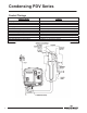
Condensing PV Series 1. Exhaust Adapter 2. Blower 3. Int. Pressure Switch 4. Exh. Pressure Switch 5. Blower Temp. Switch 6. Jacket Head 7. Surround 8. Jacket Head Insulation 9. Collector Screw Part Name and Description 12. Heat Trap Insert 23. ¾ NPT Plug 13. Hot Water Outlet 24. T & P Valve 14. Inlet Diptube 25. Screw and Washer 15. Flue Baffle 26. Exhaust Cover 16. Hex Head Anode 27. Condensate Tee 17. Vertical Exh. Pipe 28. Exhaust Gasket 18. Vertical Int. Pipe 29. Right Side Inner Door 19.