
Install Instructions

50
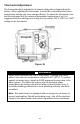
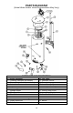
PARTS DIAGRAM
(Actual Water Heater Visual Representation May Vary)
PART NAME AND DESCRIPTION
1. Blower Assembly
14. Gas Valve
2. Pressure Switches (not shown)
15. Resistive Device
3. Blower Temp. Switch (not shown)
16. Drain Valve
4. Jacket Head
17. Inner Door (Left)
5. Top Insulation
18. Screw (Inner Door)
6. Anode-Nipple
19. Outer Door
7. Diptube-Nipple
20. Screw (Outer Door)
8. Flue Core
21. Inner Door (Right)
9. Flue Collector
22. Gas Feedline
10. Flue Baffles
23. Gas Pilot
11. Exhaust Collector/Venting
24. Gas Orifice
12. Intake Boot/Pipe
25. Burner
13. T & P Valve