
Install Instructions

29
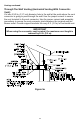
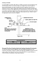
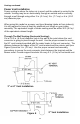
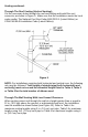
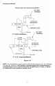
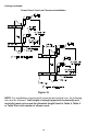
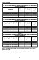
Venting continued-
TABLE 4
2” (5.1 cm) Vent Connector Lengths From Inside Wall For Low Ground
Clearance Installations
Terminating
# of
Elbows
(excl. vent
term.)
Max Straight
Length ft (m)
Min
Straight
Length
ft (m)
(2) 90 Elbows with Vent Terminal
1
30 (9.1)
5 (1.5)
(2) 90 Elbows with Vent Terminal
2
25 (7.6)
5 (1.5)
(2) 90 Elbows with Vent Terminal
3
20 (6.1)
5 (1.5)
(2) 90 Elbows with Vent Terminal
4
15 (4.6)
5 (1.5)
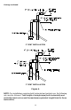
TABLE 5
3” (7.6 cm) Vent Connector Lengths From Inside Wall For Low Ground
Clearance Installations
Terminating (Reduce 3” to 2”)
(Reduce 7.6 cm to 5.1 cm)
# of
Elbows
(excl. vent
term.)
Max Straight
Length ft (m)
Min
Straight
Length
ft (m)
(2) 90 Elbows with Vent Terminal
1
100 (30.5)
10 (3.1)
(2) 90 Elbows with Vent Terminal
2
95 (29.0)
10 (3.1)
(2) 90 Elbows with Vent Terminal
3
90 (27.4)
10 (3.1)
(2) 90 Elbows with Vent Terminal
4
85 (25.9)
10 (3.1)
(2) 90 Elbows with Vent Terminal
5
80 (24.4)
10 (3.1)
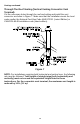
TABLE 6
4” (10.2 cm) Vent Connector Lengths From Inside Wall For Low Ground
Clearance Installations
Terminating (Reduce 4” to 2”)
(Reduce 10.2 cm to 5.1 cm)
# of
Elbows
(excl. vent
term.)
Max Straight
Length ft (m)
Min
Straight
Length
ft (m)
(2) 90 Elbows with Vent Terminal
1
160 (48.8)
10 (3.1)
(2) 90 Elbows with Vent Terminal
2
155 (47.2)
10 (3.1)
(2) 90 Elbows with Vent Terminal
3
150 (45.7)
10 (3.1)
(2) 90 Elbows with Vent Terminal
4
145 (44.2)
10 (3.1)
(2) 90 Elbows with Vent Terminal
5
140 (42.7)
10 (3.1)
HIGH ALTITUDE INSTALLATIONS FOR ELEVATIONS OVER 2,000 FEET (762 m)
ABOVE SEA LEVEL
The capacity of the induced draft blower declines with increasing altitude due to a
reduction in the air density. In order to assure safe and reliable performance of the water
heater, contact the supplier for a high-altitude kit.