
Install Instructions


11
Venting continued-
This water heater has a certified category IV, per latest ANSI Z 21.10.3-2015.CSA
4.3-2015 revision. Refer to the latest edition of the National Fuel Gas Code (ANSI
Z223.1-latest edition), or in Canada, the Natural Gas and Propane installation Code
(B149.1-00 latest edition).
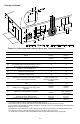
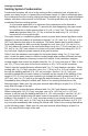
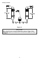
Power Direct Vent Terminal Location
Plan the vent system layout so that proper clearances are maintained from
plumbing and wiring. Before the vent is installed, determine the vent pipe
termination location as shown in Figure 1a.
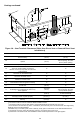
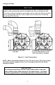
Power Vent Terminal Location
Plan the vent system layout so that proper clearances are maintained from
plumbing and wiring. Before the vent is installed, determine the vent pipe
termination location as shown in Figure 1b.
NOTICE
Before beginning installation of any vent pipe, read the vent pipe manufacturer’s
installation instructions.
DO NOT install the water heater in any location where the ambient temperature may
fall below freezing. Water heater must be protected from freezing downdrafts during
shutdown periods.
Provide protection of the building materials from degradation by flue gases from the
exhaust vent terminal.
The vent shall terminate a minimum of 12 in. (30.5 cm) above expected snowfall level
to prevent blockage of vent termination.
The horizontal centerline of the exhaust vent terminal (if applicable) must not be
located lower than the horizontal centerline of the air intake terminal if vented through
the same wall.
A service drain loop must be installed in the drain tubing to serve as a condensate
trap to prevent flue gases from escaping into the room.
DO NOT position the air intake above the exhaust terminal.
NEVER locate the air intake where exhaust gases can be introduced.