CONDENSING POWER (DIRECT) VENT GAS WATER HEATER A Spanish language version of these instructions is available by contacting the company listed on the rating plate. Hay disponible una versión en español de estas instrucciones al comunicarse con la compañía que se menciona en la placa de datos de servicio. INSTALLATION AND OPERATION INSTRUCTION MANUAL WARNING: If the information in these instructions is not followed exactly, a fire or explosion may result causing property damage, personal injury, or death.
CONGRATULATIONS! You have purchased one of the finest water heaters on the market today! This installation and operation manual will explain in detail the installation and maintenance of your new Condensing Power Vent/Power Direct Vent Gas Water Heater. We strongly recommend that you contact a plumbing professional for the installation of this water heater. We require that you carefully read this manual, as well as the enclosed warranty, and refer to it when questions arise.
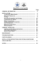
TABLE OF CONTENTS Page GENERAL INFORMATION ................................................................. 4 INSTALLATION. .................................................................................. Locating the Water Heater........................................................... Minimum Clearances ................................................................... Venting ..........................................................................................
GENERAL INFORMATION This gas-fired water heater is design certified by CSA International under the American National Standard Z21.10.3 and CAN/CGA 4.3-M most current editions at the time of manufacture. This is a category IV water heater. This water heater must be installed in accordance with local codes or, in the absence of local codes, the National Fuel Gas Code, ANSI Z223.1-Latest Edition) and/or in Canada CAN/CGA B149 Installation Codes (Latest Editions).
General Information continued- Sacrificial anodes are used to extend tank life. Anode removal, except for inspection and/or replacement, will nullify the warranty. In areas where water is unusually active, an odor may occur at the hot water faucet due to a reaction between the sacrificial anodes and the impurities in the water. If this should happen, alternative anodes may be purchased from the supplier that installed this water heater. This will minimize the odor while protecting the tank.
INSTALLATION Locating the Water Heater WARNING Water heaters are heat producing appliances. To avoid damage or injury, DO NOT store materials against the water heater or vent-air intake system. Use proper care to avoid unnecessary contact (especially by children) with the water heater and vent-air intake components.
Installation (Locating the Water Heater) continued- NOTE: Damage to the water heater caused by exposure to corrosive vapors is not covered by the warranty. DO NOT operate the water heater if exposure has or will occur. DO NOT store any potentially corrosive compounds in the vicinity of the water heater.
Installation (Locating the Water Heater) continuedThe water heater must be located close enough to the outside wall to keep the venting distance within the maximum distance described in the installation instructions. Locate the water heater as close as possible to the vent opening. Read the venting section in this instruction manual before locating the water heater.
Venting The venting instructions must be followed to avoid restricted combustion or recirculation of flue gases. Such conditions cause sooting or risks of fire and asphyxiation. This water heater can be installed as either a power direct vent system or power vent (air from inside) system. If it is installed as a direct vent system, then the air intake and the exhaust vent are piped to the outside. If a power vented system is used, then air is drawn from inside and only the exhaust is piped to the outside.
Venting continued- WARNING Risk of carbon monoxide poisoning or fire due to joint separation or pipe breakage. This water heater must be properly vented and connected to an approved vent system in good condition. DO NOT operate the water heater with the absence of an approved vent system. A clean and unobstructed vent system is necessary to allow noxious fumes that could cause injury or loss of life to vent safely and will contribute toward maintaining the water heater’s efficiency.
Venting continued- NOTICE Before beginning installation of any vent pipe, read the vent pipe manufacturer’s installation instructions. DO NOT install the water heater in any location where the ambient temperature may fall below freezing. Water heater must be protected from freezing downdrafts during shutdown periods. Provide protection of the building materials from degradation by flue gases from the exhaust vent terminal. The vent shall terminate a minimum of 12 in. (30.
Venting continued- Figure 1a – Direct Vent and Powered Direct Vent Terminal Clearances A= Clearance above grade, veranda, porch, deck or balcony B= Clearance to window or door that may be opened Canadian Installations1 12 inches (30 cm) 12 inches (30 cm) US Installations2 12 inches (30 cm) 12 inches (30 cm) C= Clearance to permanently closed window *b *b D= Vertical clearance to ventilated soffit located above the terminal within a horizontal distance of 2 feet (61 cm) from the center line of t
Venting continued- Figure 1b – Vent Terminal Clearances (Other than Direct Vent or Powered Direct Vent Installations) Canadian Installations1 US Installations2 A= Clearance above grade, veranda, porch, deck or balcony 12 inches (30 cm) B= Clearance to window or door that may be opened 12 inches (30 cm) 12 inches (30 cm) 4 feet (1.
Venting continuedThe vent system must terminate so that proper clearances are maintained as cited in local codes or the Latest Edition of the National Fuel Gas Code, ANSI Z223.1.73.4e and 7.8a, b as follows: 1. Do not terminate near soffit vents or crawl space or other area where condensate or vapor could create a nuisance or hazard or cause property damage. 2.
Venting continued- Venting System Condensation Condensate formation will occur in the venting of this condensing unit, whether as a power vent water heater or a power direct vent water heater. In order to effectively drain the condensate from the venting, tubing has been installed on a factory supplied exhaust adapter with drain outlet mounts on the blower. The tubing will drain any accumulated condensate from the venting system.
Venting continuedTABLE 1 – VENT CONNECTOR LENGTHS FOR 2” (5.1 cm) DIAMETER VENT PIPE Terminating # of 90° Elbows (excl. vent term) Maximum straight Length ft (m) Min. straight Length ft (m) Through the Wall Through the Wall Through the Wall Through the Wall Through the Roof Through the Roof Through the Roof Through the Roof Through the Roof 1 2 3 4 0 1 2 3 4 45 (13.7) 40 (12.2) 35 (10.7) 30 (9.1) 50 (15.2) 45 (13.7) 40 (12.2) 35 (10.7) 30 (9.1) 2 (.6) 2 (.6) 2 (.6) 2 (.6) 7 (2.1) 7 (2.1) 7 (2.
Venting continued- NOTICE The air intake and exhaust terminals may be located on separate outside walls or one terminal may exit the roof while the other is through the wall. The total combined equivalent vent length must be within the limits specified in the venting tables and the intake length cannot exceed the exhaust by more than 30 ft. (9.2 m). Connection to 2 in. (5.1 cm) vent pipe Connection to a 2 in. (5.1 cm) to 3 in. (7.6 cm) reducer or 4 in. (10.
Venting continued- Power Direct Vent Through The Wall Venting (Horizontal Venting With Standard Vent Terminals): Cut two 2 1/2 in. (6.4 cm) diameter holes in the wall at the point where the vent connector is going to pass through the wall. Use the proper cement to secure the 45° vent terminal provided with the water heater to the vent connector. The distance between the edges of the 45° vent terminal and the exterior wall must be 1 in. (2.5 cm) (see Figure 3).
Venting continued- Vent Terminal Configurations For Through The Wall Venting: When venting through the wall, the exhaust terminal must exit the structure at a minimum distance of 16 in. (40.6 cm) from the intake terminal. The exhaust terminal must not be located below the intake terminal for any reason (see Figure 4a below for examples of acceptable vent terminal configurations).
Venting continued- Figure 4c IMPORTANT When using the vent terminal configuration shown in Figure 4c the extra elbows must be accounted for in the total vent length see Table 4 or Table 5.
Venting continued- Through The Wall Venting (Horizontal Venting With Concentric Vent): Cut one 3 5/8 in. (11.7 cm) diameter hole in the wall at the point where the vent connector is going to pass through the wall. Use the proper cement to secure the vent terminal to the vent connector. Use the proper cement and assembly procedures to secure the vent connector joints between the terminal and the blower outlet. Provide support brackets for every 5 ft. (1.5 m) of horizontal vent.
Venting continued- It is acceptable to install a 90º elbow on IPEX concentric vent terminations use with this power direct vent water heater (see Figure 5b). A short length of appropriate diameter vent pipe should be used to transition from the vent terminal to the 90º elbow. Approved venting materials along with primers and cements are listed at the beginning of this venting section.
Venting continued- 2” VENT INSTALLATION 3” VENT INSTALLATION Figure 6 NOTE: For installations requiring both horizontal and vertical runs, the following rule must be followed: Total length of straight pipe (both horizontally and vertically) must not exceed the maximum equivalent length listed in these instructions.
Venting continued- Through The Roof Venting (Vertical Venting Concentric Vent Terminal): Cut the necessary holes through the roof and ceiling and install the vent connector as shown in Figure 7. Make sure that the installation meets the local codes and/or the National Fuel Gas Code ANSI Z223.1 (Latest Edition) or CAN/CGA B149 installation code (latest edition).
Venting continued- Power Vent Installation Power venting is where the indoor air is used, and the exhaust is vented to the outside. Venting may be run horizontally through an outside wall or vertically through a roof through using either 2 in. (5.1 cm), 3 in. (7.7 cm), or 4 in. (10.2 cm) diameter pipe. When using this model as a power vent type (drawing intake air from indoors), it is still required to have at least the minimum vent length on your intake assembly.
Venting continuedThrough The Roof Venting (Vertical Venting): Cut the necessary holes through the roof and ceiling and install the vent connector as shown in Figure 9. Make sure that the installation meets the local codes and/or The National Fuel Gas Code ANSI Z223.1 (Latest Edition) or CGA/CAN B149 Installation Code (Latest Edition).
Venting continuedPower Vent Low Clearance Installation 2” Vent Installation 3” or 4” Vent Installation Figure 10 NOTE: For installations requiring both horizontal and vertical runs, the following rule must be followed: Total length of straight pipe (both horizontally and vertically) must not exceed the allowable length listed in Table 4, Table 5 or Table 6 for total number of elbows used.
Venting continued- Power Direct Vent Low Clearance Installation Figure 11 NOTE: For installations requiring both horizontal and vertical runs, the following rule must be followed: Total length of straight pipe (both horizontally and vertically) must not exceed the allowable length listed in Table 4, Table 5 or Table 6 for total number of elbows used.
Venting continued- TABLE 4 2” (5.1 cm) Vent Connector Lengths From Inside Wall For Low Ground Clearance Installations # of Min Elbows Straight Max Straight Terminating (excl. vent Length Length ft (m) term.) ft (m) 1 30 (9.1) 5 (1.5) (2) 90 Elbows with Vent Terminal 2 25 (7.6) 5 (1.5) (2) 90 Elbows with Vent Terminal 3 20 (6.1) 5 (1.5) (2) 90 Elbows with Vent Terminal 4 15 (4.6) 5 (1.5) (2) 90 Elbows with Vent Terminal TABLE 5 3” (7.
PV/PDV Vent Pipe Preparation and Joining Most failures in vent systems result from improper preparation and joining of pipe and fittings. The guidelines below must be followed when installing the venting system. If you have any question about the application or installation of the venting system, contact the vent pipe manufacturer, supplier, or your plumbing professional. 1) 2) 3) 4) Specific cleaners, solvents, primers and cements are available for PVC, CPVC, and ABS pipe.
Combustion Air Supply WARNING Liquefied petroleum gas/propane gas is heavier than air and will remain at floor level if there is a leak. Basements, crawl spaces, closets and areas below ground level will serve as pockets for accumulation of leaking gas. Before lighting, smell all around the appliance area for gas. Be sure to smell next to the floor. IF YOU SMELL GAS: • DO NOT try to light any appliance. • DO NOT touch any electric switch; do not use any telephone in your building.
Installation (Combustion Air Supply) continued- All Air From Inside the Building The confined space must be provided with two permanent openings communicating directly with an additional room(s) of sufficient volume so that the combined volume of all spaces meets the criteria for an unconfined space. The total input of all gas utilization equipment installed in the combined space must be considered in making this determination. Each opening must have a minimum free area of 1 in.²/1000 BTU (6.5 cm2/0.
Water Connections NOTE: BEFORE PROCEEDING WITH THE INSTALLATION, CLOSE THE MAIN WATER SUPPLY VALVE. After shutting off the main water supply, open a faucet to relieve the water line pressure to prevent any water from leaking out of the pipes while making the water connections to the water heater. After the pressure has been relieved, close the faucet. The COLD water inlet and HOT water outlet are identified on the top of the water heater.
Water Connections continued- WARNING For protection against excessive temperatures and pressure, install temperature and pressure protective equipment required by local codes, but not less than a combination temperature and pressure relief valve certified by a nationally recognized testing laboratory that maintains periodic inspection of production of listed equipment or materials as meeting the requirements of the Standard for Relief Valves and Automatic Gas Shutoff Devices for Hot Water Supply Systems, A
Water Connections continued- WARNING Hydrogen gas can be produced in an operating water heater that has not had water drawn from the tank for a long period of time (generally two weeks or more). Hydrogen gas is extremely flammable. To prevent the possibility of injury under these conditions, we recommend the hot water faucet to be open for several minutes at the kitchen sink before you use any electrical appliance which is connected to the hot water system.
Condensate Drain Connection This is a condensing water heater and requires a drain to allow the condensate to discharge safely. If a drain is not in close proximity, a condensate pump may be required to pump the condensate to the closest drain. A self-priming trap is integrated in the condensate/pressure tube, allowing the connection to the ½” (1.3 cm) port to run directly to the drain without an external trap connected. The preferred connection to the condensate port is with plastic pipe and fittings.
Gas Connections WARNING Prior to connecting the gas supply line to a gas fired water heater, ensure that the gas supply line DOES NOT have moisture/water or dirt/scale inside the gas line. Commonly this check is done at the lowest point in the gas distribution system prior to gas burning appliances. The gas supply lines must meet all requirements of the National Fuel Gas Code (ANSI Z223.1-Latest Edition), or in Canada CAN/CGA B149.1 Natural Gas Installation Code (Latest Edition) or CAN/CGA B149.
Gas Connections continued- CAUTION The water heater and individual shutoff valve must be disconnected from the gas supply piping system during any pressure testing of the system at test pressures in excess of 1/2 psi (3.5 kPa). The water heater must be isolated from the gas supply piping system by closing its manual shutoff valve during any pressure testing of the gas supply system at test pressures equal to or less than 1/2 psi (3.5 kPa).
Wiring Diagram Figure 13 39
GENERAL OPERATION WARNING Water heaters are heat producing appliances. To avoid damage or injury there must be no materials stored against the water heater or vent-air intake system, and proper care must be taken to avoid unnecessary contact (especially by children) with the water heater and vent-air intake system.
Lighting and Shutdown Instructions Figure 14 41
Thermostat Adjustment The thermostat dial is adjusted to its lowest setting when shipped from the factory. When adjusting the thermostat, it should be remembered that lower temperature settings are more energy efficient. To adjust the thermostat, turn the dial clockwise until the minimum acceptable temperature is set. It is suggested that the starting point setting not exceed the 120°F (49°C) or “HOT” setting on the thermostat. Figure 15 DANGER Hotter water increases the risk of scald injury.
Burner Flame Check Steel Burner: These models are equipped with self-adjusting air mixture and do not have an adjustable air shutter (see Figure 16). At periodic intervals a visual check of the main burner and pilot flames should be made to determine if they are burning properly. The main burner flame should light smoothly from the pilot. Figure 16 WARNING DO NOT run out of propane gas. Damage to the water heater may occur.
MAINTENANCE WARNING Water heaters are heat producing appliances. To avoid damage or injury there must be no materials stored against the water heater or vent-air intake system, and proper care must be taken to avoid unnecessary contact (especially by children) with the water heater and vent-air intake system.
Maintenance continued- 5. Annually remove the inner door and main burner assembly to clean orifices and related parts of any dirt or other foreign material. Inspect the burner ports for obstructions or debris and clean with a wire brush as needed. Wire brush and/or vacuum clean the combustion chamber as needed to remove scale deposits and debris. NOTE: It is imperative for proper operation of the water heater that the inner door be replaced in the original location.
Maintenance continued- CAUTION FOR YOUR SAFETY, DO NOT ATTEMPT REPAIR OF GAS CONTROL, BURNERS OR GAS PIPING. REFER REPAIRS TO A QUALIFIED SERVICE TECHNICIAN. Contact your supplier or plumbing professional for replacement parts or contact the company at the address given on the rating plate of the water heater. Provide the part name, model and serial numbers of the water heater when ordering parts. READ THE WARRANTY FOR A FULL EXPLANATION OF THE LENGTH OF TIME THAT PARTS AND THE WATER HEATER ARE WARRANTED.
Troubleshooting LED Status Control Status None (LED not on or flashing) Electrical power not present. Stand-by mode, Thermostat is satisfied (no faults). One short flash every four seconds Alternates bright and dim (Heartbeat) Thermostat calling for heat (no fault). Short flash once every second Weak pilot signal on last call for heat. Short flash once every two seconds Idle remote command off. Pressure switch not working-closed position.
Troubleshooting continued- LED Status Control Status Six flashes-two flashes, three second pause (Soft lockout) Pressure switch or blower temperature switch opened during burner operation. System auto resets after 5 minutes. 1. Pressure switch tubing kinked or blocked. 2. Vent blockage or improper vent configuration. 3. Vent termination being affected by windy conditions. 4. Blower not spinning up to speed. 5. Vent temperature too high. 6. Faulty pressure switch or blower temperature switch.
Control Sequence of Operation Start-up Sequence Upon powering up, the control checks for the presence of the resistive plug. If the resistance is in the expected range, the control will begin normal operation after 5 to 8 seconds. Normal Heating Sequence 1. The thermostat senses a need for heat. 2. The control checks the pressure switch condition. 3. If the pressure switch is open, the control sends power to the blower motor. 4. The blower starts moving combustion air through the combustion system. 5.
PARTS DIAGRAM (Actual Water Heater Visual Representation May Vary) PART NAME AND DESCRIPTION 1. Blower Assembly 2. Pressure Switches (not shown) 3. Blower Temp. Switch (not shown) 4. Jacket Head 5. Top Insulation 6. Anode-Nipple 7. Diptube-Nipple 8. Flue Core 9. Flue Collector 10. Flue Baffles 11. Exhaust Collector/Venting 12. Intake Boot/Pipe 13. T & P Valve 14. Gas Valve 15. Resistive Device 16. Drain Valve 17. Inner Door (Left) 18. Screw (Inner Door) 19. Outer Door 20. Screw (Outer Door) 21.
THE FOLLOWING INSTRUCTIONS ARE FOR INSTALLATION OF GAS WATER HEATERS SUITABLE FOR WATER (POTABLE) HEATING AND SPACE HEATING: 1. All piping components connected to this water heater for space heating applications must be suitable for use with potable water. In Massachusetts, space heating piping length must not exceed 50 feet. 2. Toxic chemicals, such as those used for boiler treatment, must not be introduced into potable water used for space heating. 3.
NOTES 52