
Spec Sheet

©2017, Bradford White Corporation. All rights reserved.
Sales / Technical Support 866-690-0961 / 905-203-0600
l
Fax 905-636-0666 / www.bradfordwhite.com
For U.S. and Canada field service, contact your professional installer or local Bradford White sales representative.
Sales 800-523-2931
l
Fax 215-641-1670 / Technical Support 800-334-3393
l
Fax 269-795-1089
l
Warranty 800-531-2111
l
Fax 269-795-1089
International: Telephone 215-641-9400
l
Telefax 215-641-9750 / www.bradfordwhite.com
Ambler, PA
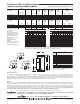
Immersion and Surface Mounted Models
Meet or exceed ASHRAE 90.1b (current standard) C.E.C. Listed
Model
Number
C
Height
to T&P
Conn.
in.
B
Jacket
Dia.
in.
A
Height
in.
U.S.
Gal.
Capacity
M-II-50(A)-kW-3SF
M-II-80(A)-kW-3SF
M-II-120(A)-kW-3SF
50
80
119
Imp.
Gal. Std. ASME
42
67
100
302
378
485
47
3
/4
60
1
/4
64
1
/2
F
Floor to
Top of
Control Box
in.
46
1
/2
46
1
/2
50
1
/4
24
26
30
1
/4
41
52
1
/2
55
49
1
/4
61
3
/4
66
D
Floor to
Hot Water
Outlet
in.
Model
Number
C
Height
to T&P
Conn.
mm.
B
Jacket
Dia.
mm.
A
Height
mm.
Liters Std. ASME
Capacity
M-II-50(A)-kW-3SF
M-II-80(A)-kW-3SF
M-II-120(A)-kW-3SF
189
303
450
137
171
220
Approx.
Shipping
Weight
lbs.
270
335
430
Approx.
Shipping
Weight
kg.
122
152
195
1213
1530
1638
F
Floor to
Top of
Control Box
mm.
1181
1181
1276
610
660
768
1041
1334
1397
Water
Conn.
Dia.
in.
1
1
/2
1
1
/2
1
1
/2
Water
Conn.
Dia.
mm.
38
38
38
1251
1568
1676
D
Floor to
Hot Water
Outlet
mm.
6
3
/4
6
3
/4
6
3
/4
E
Floor to
Cold Water
Inlet
in.
178
178
178
E
Floor to
ColdWater
Inlet
mm.
Commercial Electric Water Heater
Model numbers shown
are for Surface Mount
thermostats.
For Immersion thermostat
change suffix “SF” to “CF”.
Voltage and phase must be
specified when ordering.
Example: M-II-50-12-3SF,
240 Volt, 3 phase.
(A) ASME Construction
available.
For ASME construction add
“A” to the model number.
Example: M-II-50A-12-3SF.
Recovery
GPH Temperature Rise °F
kW Input
6
9
12
13.5
15
18
24
27
30
36
45
54
40
62
93
124
140
155
186
248
279
310
372
465
558
50
50
74
99
112
124
149
199
223
248
298
372
447
60
41
62
83
93
103
124
164
186
207
248
310
372
70
35
53
71
80
89
106
142
160
177
213
266
319
80
31
47
62
70
78
93
124
140
155
186
233
279
90
28
42
55
62
69
83
110
124
138
165
207
248
100
25
37
50
56
62
74
99
112
124
149
186
223
120
21
31
41
47
52
62
83
93
103
124
155
186
140
18
27
35
40
44
53
71
80
89
106
133
160
208V
Phase
Number of Elements (Fused Models)*
13
3(2)
3
3
3
3
3
4
6
6
6
9
9
3
3
3
3
3
3
6
6
6
6
9
9
240V
Phase
13
3(2)
3
3(2)
3
3
3
4
6
6
6
9
9
3
3
3
3
3
3
6
6
6
6
9
9
480V
Phase
13
3(2)
3
3(2)
3
3
3
4
6
6
6
9
9
3
3
3
3
3
3
6
6
6
6
9
9
277V
Phase
1
3
3
3
3
3
3
4
6
6
6
9
9
380V
Phase
3
3
3
3
3
3
3
6
6
6
6
9
9
415V
Phase
3
3
3
3
3
3
3
6
6
6
6
9
9
600V
Phase
3
3
3
3
3
3
3
6
6
6
6
9
9
Input
kW
6
9
12
13.5
15
18
24
27
30
36
45
54
208V
Phase
Full Load Current Amperes (Fused Models)*
13
28.8
43.2
57.6
64.9
72.1
86.5
115.4
129.8
144.2
173.0
216.3
259.6
16.6
25.0
33.3
37.5
41.6
50.0
66.7
75.0
83.3
100.0
125.0
150.0
240V
Phase
13
25.0
37.2
50.0
56.2
62.5
72.0
100.0
112.5
125.0
150.0
187.5
225.0
14.4
21.6
28.9
32.5
36.1
43.4
57.8
65.0
72.2
86.7
108.3
130.0
480V
Phase
13
12.5
18.7
25.0
28.1
31.2
37.5
50.0
56.2
62.5
75.0
93.7
112.5
7.2
10.8
14.4
16.2
18.0
21.6
28.9
32.5
36.1
43.3
54.1
65.0
277V
Phase
1
21.6
32.4
43.3
48.7
54.1
64.0
86.6
97.4
108.3
129.9
162.4
194.9
380V
Phase
3
10.0
14.0
19.0
21.0
23.0
28.0
37.0
41.0
46.0
55.0
69.0
83.0
415V
Phase
3
9.0
13.0
17.0
19.0
21.0
25.0
34.0
38.0
42.0
50.0
63.0
75.0
600V
Phase
3
5.8
8.7
11.5
13.0
14.4
17.3
23.1
26.0
28.9
34.6
43.3
52.0
Input
kW
6
9
12
13.5
15
18
24
27
30
36
45
54
F
E
C
D
A
B
HOT
COLD
45°
15 1/8"
22 1/8"
19 1/2"
HOT
COLD
52°
13"
56°
T & P
47°
T & P
HOT
COLD
58°
12"
18 1/2"
63°
T & P
HOT
COLD
45°
15 1/8"
22 1/8"
19 1/2"
HOT
COLD
52°
13"
56°
T & P
47°
T & P
HOT
COLD
58°
12"
18 1/2"
63°
T & P
Optional surface thermostats ranging from
80°F to 140°F are available.
Non-ASME units with amperage draw of 48 amps or more require factory installed internal fusing and ASME units
with amperage draw of 120 amps or more require factory installed internal fusing. *If the number of elements on
non-fused models is different, it is located in parentheses ( ), following the amp draw.
Sample Specification
The water heater shall be a Bradford White model with a rated storage capacity of not less than_______gallons (_______liters), a minimum kW input of
_______kW (_______ BTU/Hr.), a minimum recovery of _______GPH (_______ LPH). The tank shall be Vitraglas
®
lined and have a bolted hand hole cleanout.
The tank shall have _______magnesium anode rods installed in separate tank head couplings. The heater shall have 3" Non-CFC foam insulation, and come
equipped with an ASME rated T&P relief valve, a cold water inlet Hydrojet
®
Sediment Reduction System. It shall be design certified by ETL for 180ºF (82ºC)
application, either with or without a separate storage tank, and comply with state and local codes and ordinances.
General
All electric water heaters are certified at 300 PSI test pressure (2068 kPa) and 150 PSI working pressure (1034 kPa). All models are design certified by ETL,
to provide outlet water at a thermostatically controlled temperature greater than 180°F (82°C) as an Automatic Storage Heater, and an Automatic Circulating
Tank Heater. As an Automatic Storage Heater, all models are complete, self-contained water heating systems. It needs no separate storage tank, pump,
wiring or elaborate piping network. When equipped with a mixing valve, it will supply 180°F (82°C) sanitizing and lower temperature general purpose hot
water simultaneously. These models can be used either as a single unit or in multiples connected in series or parallel (recommended). Dimensions and
specifications subject to change without notice in accordance with our policy of continuous product improvement.
Printed in U.S.A.401/402B-1117-A