GAS-FIRED WATER HEATER A Spanish language version of these instructions is available by contacting the company listed on the rating plate. La versión espãnola de estas instrucciones se puede obtener al escribirle a la fábrica cuyo nombre aparece en la placa de especificaciones.
CONGRATULATIONS! You have just purchased one of the finest water heaters on the market today! This installation, operation and instruction manual will explain in detail the installation and maintenance of your new Gas Water Heater. We strongly recommend that you contact a plumbing professional for the installation of this water heater. We require that you carefully read this manual, as well as the enclosed warranty, and refer to it when questions arise.
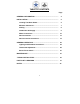
TABLE OF CONTENTS Page GENERAL INFORMATION ............................................................ 4 INSTALLATION ............................................................................. 5 Locating The Water Heater .................................................... 5 Minimum Clearances .............................................................. 7 Venting .................................................................................... 8 Combustion Air Supply .....................
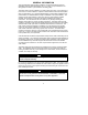
GENERAL INFORMATION This gas-fired water heater is design certified by the CSA International under the applicable American National Standard, Z21.10.1 or Z21.10.3-(as indicated on the rating plate) and CSA 4.1-(as indicated on the rating plate). This water heater must be installed in accordance with local codes. In the absence of local codes, it must be installed in compliance with the National Fuel Gas Code (ANSI Z223.1-Latest Edition), or in Canada CAN/CGA B149.
General Information continuedTo comply with NSF requirements this water heater is to be: a) Sealed to the floor with sealant, in a smooth and easily cleanable way, or b) Installed with an optional leg kit that includes legs and/or extensions that provide a minimum clearance of 6” beneath the water heater. This water heater has been manufactured for operation at altitudes from sea level to 2000 feet (610m) (unless otherwise specified on the water heater).
Installation continued- DO NOT install the water heater in any location where gasoline or flammable vapors are likely to be present. This water heater MUST be installed indoors out of the wind and weather. The location of this water heater is of the utmost importance. Before installing this water heater, read the installation section of these instructions.
Installation continued- WARNING DO NOT ATTEMPT TO LIGHT ANY GAS APPLIANCE IF YOU ARE NOT CERTAIN OF THE FOLLOWING: Liquefied petroleum gases/propane gas and natural gas have an odorant added by the gas supplier that aids in detection of the gas. Most people recognize this odor as a “sulfur” or “rotten egg” smell. Other conditions, such as “odorant fade” can cause the odorant to diminish in intensity, or “fade”, and not be as readily detectable.
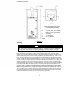
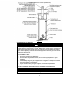
Installation continued- Minimum Clearances From Combustible Materials A 0” (0cm) Left, 2” (5.08cm) Right (113.6 Liters Only) B 0” (0cm) C 4” (10.16cm) D 78” (1.98m) m VENT ---- Figure 1 Venting WARNING The vent system must be installed properly. Failure to properly install the vent system could result in property damage, personal injury, or death. Make certain the flue baffle is in place and centered in flue tube.
TYPICAL INSTALLATION (VENTING) Figure 2 Combustion Air Supply WARNING Liquefied petroleum gases/propane gases are heavier than air and will remain at floor level if there is a leak. Basements, crawl spaces, closets and areas below ground level will serve as pockets for accumulation of leaking gas. Before lighting, smell all around the appliance area for gas. Be sure to smell next to the floor. IF YOU SMELL GAS: Do not try to light any appliance.
Combustion Air Supply continuedAll combustion air must be supplied from outdoors by one of the following installation methods and as illustrated in Figure 2. The flow of combustion and ventilating air must not be obstructed. Adequate air must be supplied for combustion and ventilation. An insufficient supply of air will cause recirculation of combustion products resulting in air contamination that may be hazardous to life.
Water connections continued- WARNING FAILURE TO INSTALL AND MAINTAIN A NEW, LISTED 3/4” X 3/4” TEMPERATURE AND PRESSURE RELIEF VALVE WILL RELEASE THE MANUFACTURER FROM ANY CLAIM WHICH MIGHT RESULT FROM EXCESSIVE TEMPERATURE AND PRESSURES. If this water heater is installed in a closed water supply system, such as the one having a back-flow preventer in the cold water supply, provisions must be made to control thermal expansion.
Water connections continued- WARNING Hydrogen gas can be produced in an operating water heater that has not had water drawn from the tank for a long period of time (generally two weeks or more). Hydrogen gas is extremely flammable. To prevent the possibility of injury under these conditions, we recommend the hot water faucet to be open for several minutes at the kitchen sink before you use any electrical appliance which is connected to the hot water system.
Gas Connections The gas supply lines must meet all requirements of the National Fuel Gas Code (ANSI Z223.1-Latest Edition), or in Canada CAN/CGA B149.1 Natural Gas Installation Code (Latest Edition) or CAN/CGA B149.2 Propane Installation Code (Latest Edition). The minimum permissible gas supply pressure for the purpose of input adjustment is one (1.0) inch (0.25 kPa) water column above the operating manifold pressure. See the rating plate and gas valve for the manifold pressure and gas type.
Gas Conversion Instructions Unless specifically ordered for operation on natural gas, this water heater is normally equipped for operation on liquefied petroleum (LP) gas but may be converted by following these gas conversion instructions. Caution: Make sure gas to be supplied to this water heater following the conversion matches the gas being converted to. CAUTION All gas conversions must be performed by qualified service personnel only. To convert from L.P.
Gas Conversion Instructions continued- b) c) d) ii) Remove (2) 1/4” hex drive screws from right side inner door. iii) Remove (2) 1/4” drive screws from flange section of inner door. iv) Remove (2) 1/4” drive screws from left side inner door. v) Remove inner door and inspect per step 4b.
Gas Conversion Instructions continued- b) c) Place the left side inner door into position first. Firmly position the radiused channel of the inner door around the feedline. Using the ¼” hex drive screws from step 4, secure left side inner door in place. DO NOT OVER TIGHTEN SCREWS. Position thermocouple, pilot tube and Piezo wire against left side inner door flange gasket. DO NOT ROUTE THROUGH RADIUSED CHANNEL WITH FEEDLINE. WARNING Stripped fastener connections may allow for seal breach of inner door.
Gas Conversion Instructions continued- To convert from L.P. gas to natural gas (For control shown in figure 4 only) 1) Rotate and partially depress gas control knob clockwise to “OFF” position. 2) Change gas regulator setting by removing cap from gas regulator. Depress and rotate plunger clockwise with a screwdriver releasing plunger. Figure 4 3) 4) Replace cap. Remove the outer door. Remove inner door as instructed below. a) Inner Door Removal.
Gas Conversion Instructions continued- c) d) If the gasket is not effected by any of the above, gasket replacement is not required. If gasket replacement is required, contact manufacturer for inner door gasket replacement kit. IMPORTANT If gasket replacement is required, contact the manufacturer for inner door gasket replacement kit. WARNING If the information in these instructions is not followed exactly, a fire or explosion may result causing property damage, personal injury or death.
Gas Conversion Instructions continued- d) Firmly place right side inner door flange against the left side inner door flange and secure with two 1/4” drive screws from step 4. DO NOT OVER TIGHTEN SCREWS. e) Align right side inner door to combustion chamber and verify the fastener holes of the combustion chamber are aligned with the right side inner door slotted opening. Verify seal integrity around combustion opening. Secure right side inner door using 1/4” hex drive screws from step 4.
Gas Conversion Instructions continued- To convert from L.P. gas to natural gas (For control shown in figure 5 only) 1) 2) 3) Rotate and partially depress gas control knob clockwise to “OFF” position. Remove the plastic cover from the regulator cap, revealing threads. The letters “LP” and “NAT” with arrows will be visible. Using an open-ended wrench, turn the regulator cap counter clockwise , until it comes off. Turn the regulator cap around so the arrow next to “NAT” is facing toward the gas valve.
Gas Conversion Instructions continued- Other imperfections that will inhibit proper seal Gasket adhesion to inner door Material left on combustion chamber (around opening) (i) Remove (2) 1/4” hex drive screws from right side inner door. (ii) Remove (2) 1/4” drive screws from flange section of inner door. (iii) Remove (2) 1/4” drive screws from left side inner door. (iv) Remove inner door and inspect per step 4b.
Gas Conversion Instructions continued- WARNING d. Firmly place right side inner door flange against the left side inner door flange and secure with two ¼” drive screws from step 4. DO NOT OVER TIGHTEN SCREWS. e. Align right side inner door to combustion chamber and verify the fastener holes of the combustion chamber are aligned with the right side inner door slotted opening. Verify seal integrity around combustion opening. Secure right side inner door using ¼” hex drive screws from step 4.
GENERAL OPERATION WARNING Water heaters are heat producing appliances. To avoid damage or injury there must be no materials stored against the water heater or vent-air intake system, and proper care must be taken to avoid unnecessary contact (especially by children) with the water heater and vent-air intake system.
Lighting and Shutdown Instructions 24
Thermostat Adjustment Figure 6 The thermostat dial is set to its lowest temperature setting when shipped from the factory. Remember that lower temperature settings are more energy efficient. Adjust the temperature by turning the thermostat dial. It is suggested that the starting point setting not be greater than the ” “ mark on the thermostat dial (approximately 120°F [48.9°C]) as pictured above. Rotate the thermostat dial clockwise to decrease the temperature setting.
Thermostat Adjustment continued Figure 8 The thermostat dial is set to its lowest temperature setting when shipped from the factory. Remember that lower temperature settings are more energy efficient. Adjust the temperature by turning the thermostat dial. It is suggested that the starting point setting not be greater than the ” “ mark on the thermostat dial (approximately 120°F [48.9°C]) as pictured above. Rotate the thermostat dial clockwise to decrease the temperature setting.
General Operation continued- Burner Flame Check Steel Burner: These models are equipped with self adjusting air mixture and do not have an adjustable air shutter (See Figure 9). At periodic intervals, a visual check of the main burner and pilot flames should be made to determine if they are burning properly. The main burner flame should light smoothly from the pilot. Figure 9 WARNING Do not run out of propane gas. Damage to the water heater may occur.
Maintenance continued- IMPORTANT The water heater should be inspected at a minimum annually by a qualified service technician for damaged components and/or joints not sealed. DO NOT operate this water heater if any part is found damaged or if any joint is found not sealed. The following maintenance should be performed by a qualified service technician at the minimum periodic intervals suggested below.
Maintenance continued- WARNING When lifting lever of the combination temperature and pressure relief valve, hot water will be released under pressure. Be careful that any released water does not result in bodily injury or property damage. WARNING THIS WATER MAY BE HOT. WARNING Do not run out of propane gas. Damage to the water heater may occur. 6. At least once a year, check the combination temperature and pressure relief valve to insure that the valve has not become encrusted with lime.
Maintenance continued- Manufactured under one or more of the following U.S. Patents: RE.34,534; B1 5,341,770; 4,416,222; 4,628,184; 4,669,448; 4,672,919; 4,808,356; 4,829,983; 4,861,968; 4,904,428; 5,000,893; 5,023,031; 5,052,346; 5,081,696; 5,092,519; 5,115,767; 5,199,385; 5,277,171; 5,372,185; 5,485,879; 5,574,822; 5,596,952; 5,660,165; 5,682,666; 5,761,379; 5,943,984; 5,954,492; 5,988,117; 6,142,216; 6,395,280; 6,684,821; 7,007,748; 7,063,132; Other U.S. and Foreign patent applications pending.
MANUFACTURED HOME (MOBILE HOME) GAS-FIRED WATER HEATER PARTS LIST PART NAME & DESCRIPTION 1. 2. 3. 4. 5. 6. 7. 8. 9. 10. 11. 12. 13. Gas Conversion Kit Jacket Head Pan Jacket Outer Door Hot Water Outlet Nipple Flue Baffle Assembly Anode Temperature and Pressure Relief Valves Glass Lined Tank Combustion Chamber Assembly Jacket Base Pan Inner Door Gasket Inner Door Assembly 31 13A. 14. 15. 16. 17. 18. 19. 20.
NOTES 32