
Spec Sheet

1" Non-CFC Foam Insulation 76% Recovery Efficiency C.E.C. Listed
Energy Saver Models
6-Year Limited Warranty on
Component Parts
BRADFORD WHITE CORPORATION has
a 6-year warranty on replaceable parts–
thermostat, burner, dip tube, drain valve.
These quality components are
manufactured for us by industry leaders
and will be replaced in the event of
failure during the parts warranty period
(exclusive of shipping and re-installation
cost).§
6 or 10-Year Limited
Tank Warranties
BRADFORD WHITE CORPORATION
LIMITED WARRANTY: Protects your
investment in a quality glass-lined
heater. If the tank leaks for reasons of
faulty materials, workmanship, or
corrosion within the warranty period, the
heater will be replaced with a compara-
ble heater of our manufacture (exclusive
of shipping and re-installation cost).§
101-B-AC-0204-A Printed in U.S.A.
Residential Energy Saver Gas-Upright
FOR MANUFACTURED HOMES ATMOSPHERIC COMBUSTION
Design evaluated in accordance with the H.U.D. Manufactured Home Construction and Safety
Standard, Title 24 CFR, Part 3280.707 (d)(2) for energy efficiency.
These water heaters meet or exceed the performance standards established under ASHRAE
Standard 90.1b (current edition).
PR ODUCTS ONLY FOR PROFESSION ALS
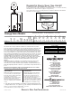
A
C
D
E
F
B
Not approved for installation where a direct vent/sealed combustion system is required.
This water heater is design certified for installation in a manufactured home (mobile
home) only and must be installed in an enclosure that will completely separate the water
heater combustion and venting system from its interior. The water heater enclosure
access door must be on the outside wall of the manufactured home (mobile home) only.
Access to the water heater enclosure from the inside of the manufactured home (mobile
home) is not permitted. The CSA International (formerly AGA/CGA) listing of this water
heater includes the field installation of the following components: roof jack, leg enclosure
(optional), air intake tube (optional), and heater tie down materials. These components
for field installation may be shipped in a separate box with the heater and must be
installed according to instructions. No other components are approved for use with the
water heater. The water heater must be installed in accordance with The Federal
Manufactured Home Construction and Safety Standard Title 24 CRF, Part 3280.
General
All gas water heaters are certified at 300 PSI (2068 kPa) test pressure and 150 PSI
(1034 kPa) working pressure. All water connections are
3
⁄4" (19mm) NPT. All gas
connections are
1
⁄2" (13mm). All models design certified by CSA International (formerly
AGA/CGA) and peak performance rated. For 10 year warranty change suffix number "6"
to "10".
Dimensions and specifications subject to change without notice in accordance
with our policy of continuous product improvement.
§ Some states do not allow limitations on warranties. For product installed in the USA,
Canada and Puerto Rico. See complete copy of the warranty included with the heater.
Vitraglas
®
is a registered trademark of Bradford White
®
Corporation.
©2004, Bradford White Corporation. All rights reserved.
Roof Jack Kits
Clearance Part Number
12" (305mm) 239-37030-01
18"/32" (457mm/813mm) 239-37030-02
32"/60" (813mm/1524mm) 239-37030-03
48"/95" (1219mm/2413mm) 239-37030-04
(Includes roof jack, hardware, instructions)
Adjustable air intake tube
(optional)
Leg enclosure kit
(optional)
Ambler, PA
Sales/
Sales/800-538-2020
800-532-4020
Fax/215-641-1670
Service/800-334-3393
Fax/269-795-1089
Warranty/800-531-2111
Fax/269-795-1089
International:
T
T
elephone/215-641-9400
elefax/215-641-9750
888-538-7833
Fax on Demand:
bradfordwhite.comwww.
Sales/866-690-0961
905-238-0100
Fax/905-238-0105
Service/800-334-3393
Mississauga, ON
www.bradfordwhitecanada.com
M-1-MH30T6LX
M-1-MH40T6LX
A
Floor to
Flue Conn.
in. mm.Liters
U.S.
Gal.
Cap.
Recovery
50˚C Rise
90˚F Rise
Nat. &
LP BTU
Input
KW
Input
Approx.
Shipping
Weight
Lbs. Kg.
Imp.
Gal.
Cap.
Imp.
GPH
U.S.
GPH
Liters/
Hour
B
Jacket
Dia.
in. mm.
C
Vent
Size
in. mm.
E
Floor to
Gas
Conn.
in. mm.
G
Floor to
HW
Conn.
in. mm.
D
Floor to
T&P
Conn.
in. mm.
32,000
34,000
9.4
10.0
114
151
30
40
58
5
⁄8
59
1
⁄8
1489
1502
106
128
48
58
25
33
27
29
33
35
125
132
60
3
⁄8
60
7
⁄8
1534
1546
50
7
⁄8
50
7
⁄8
1292
1292
14
14
356
356
16
18
406
457
3
3
76
76
F
Floor to
CW
Conn.
in. mm.
23
23
584
584