
Installation / Operation Instruction Manual

39
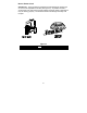
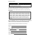
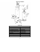
PARTS LIST DRAWING
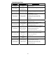
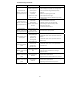
PARTS LIST
PART NAME AND DESCRIPTION
1. Blower Assembly 14. T&P Relief Valve
2. Temp. Switch 15. Pilot Assembly
3. Pressure Switch 16. Adapter
4. Flue Baffle 17. Main Burner Orifice
5. Honeywell Gas Control Valve 18. Gas Feedline
6. Drain Valve 19. Flammable Vapors Sensor
7. Fiberglass Insulation (not shown) 20. Sensor Harness
8. Foam Insulation (not shown) 21. Inner Door Assembly
9. Outer Door 22. Blower Harness
10. Steel Burner 23. Insulation Space Heat
11. Diptube–Nipple 24. Insulation Fitting
12. Anode–Nipple 25. Insulation T & P
13. Pipe Insulation