
Install Instructions

27
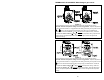
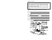
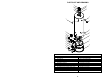
PARTS LIST AND DRAWING
PART NAME AND DESCRIPTION
1. Draft Diverter 13. Hex Screw 10-12 x 3/4
2. Hole Closure 14. Radiation Shield
3. Flue Reducer 15. Inner Door (Right Side)
4. Magnesium Anode 16. Hex Screw 8-15 x 3/4
5. Nipple 17. Outer Door
6. Flue Baffle Assembly 18. Combustion Chamber
7. Dip Tube-Cold Water Inlet 19. Steel Burner
8. Escutcheon 20. Orifice
9. Temperature and Pressure Relief Valve 21. Gas Burner Feedline
10. Combination Gas Control and Thermostat 22. Jacket Base Pan
11. Drain Valve 23. Pilot Assembly
12. Inner Door (Left Side)
1
3
5
6
11
12
17
19
20
21
22
18
14
9
8
7
4
2
10
15
13
16
23
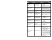
2
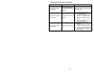
2
8