
Roof Jack Instruction

ROOF JACK & AIR INTAKE INSTALLATION INSTRUCTIONS
(FOR MANUFACTURED HOME CLOSED COMBUSTION WATER HEATERS)
Step 10. Align the water heater flue with the opening in the ceiling and roof.
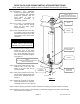
Step 11. Apply a non-hardening mastic on the roof around the opening to form a weather seal with the roof jack flashing.
Step 12. Insert the roof jack into the opening in the roof and ceiling and fasten the flashing of the roof jack to the roof
with the sheet metal screws provided. Apply additional mastic to complete the weather seal (see Figure 4).
Step 13. If optional ceiling plate is used, place over outer pipe against ceiling and secure with (4) screws (see Figure 4).
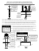
Step 14. Slip the
ø3” vent connector extension (shipped telescoped in the roof jack) down
over the flue pipe which extends above the water heater (see Figure 5).
Step 15. The vent joints must be sealed after the vent kit is installed. This kit will include a
tube of silicone or silicone band(s) to be used for sealing the vent joints.
Step 16. Clamp the vent connector extension to the water heater flue pipe with the clamp
provided (see Figure 5).
CAUTION
Silicone has a strong odor
and should have adequate
ventilation until cured.
Refer to the manufacturers
instructions for adequate
drying time.
Figure 2
AIR INTAKE SEAL
ADJUSTABLE
AIR INTAKE
ADJUSTMENT
SCREW
Figure 3
AIR INTAKE
INSERTION
TOP OF AIR
INTAKE
FLOOR
UNDERSIDE
SHEATHING
AIR INTAKE
AIR INTAKE
SEAL
Figure 5
TOP OF
WATER HEATER
FLUE CLAMP
SEAL ALL VENT CONNECTIONS
AND JOINTS WITH SILICONE OR
BAND(S) PROVIDED
TELESCOPING VENT
CONNECTOR MUST OVERLAP
FLUE PIPE COMPLETELY
NOTICE
The outer pipe MUST extend below
the ceiling as noted on the outer
pipe of the roof jack (see Figure 4).
PAGE 2
Figure 4
DRAFT HEAD
STACK BODY
ROOF
CEILING
OUTER PIPE
CEILING
PLATE
TELESCOPING
FLUE PIPE