
Installation / Operation Instruction Manual

13
Electrical Connections
Before any electrical connections are made, be sure that the water heater is
full of water and that the manual shut-off valve in the cold-water supply line is
open. Check the rating plate and wiring diagram before proceeding. This
electric water heater was built and wired in accordance with the UL testing
approvals requirements. The temperature limiting device is of the manual
reset, trip-free type and has been factory installed to interrupt all ungrounded
power supply conductors in the event of thermostat failure. Thermostats are
factory set and wired in accordance with the wiring diagram fastened to the
inside of the top access panel. The plumbing supplier in your area ordered
this heater wired at the factory to comply with existing area codes, but local
utility codes may require or allow other circuitry. The thermostats are factory
set and wired in accordance with the wiring diagram affixed to the water
heater next to the thermostat/element access cover. Consult your local
power company to determine the correct electrical hook-up in order to meet
local utility and building codes and in order to obtain the most economical
rates. Also check to find out if you are required to obtain a permit before
starting the installation. Note: Install electric connections according to
local codes or latest edition of National Electrical Code NFPA 70.
The water heater must be well grounded. The green ground wire from the
power supply shall be attached to the terminal marked for this purpose on
the terminal block for all water heaters except 10 and 15 gallon utility models.
For 10 and 15 gallon utility models, the ground wire shall be attached to the
green ground screw located under the element access cover.
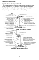
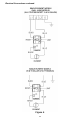
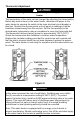
Upright and lowboy models are wired for “unbalanced” three phase delta
branch circuit operation. Upright and lowboy models (only) may be converted
to single phase and/or simultaneous operation as shown on the wiring
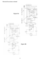
diagram (see figure 3A and 3B). To ensure proper electrical connection,
check the voltage and wiring configuration on the rating plate located on the
front of the water heater.
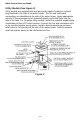
Run the power leads from an adequately fused disconnect switch (not
supplied) and connect the wires to the water heater according to the wiring
diagram found in these installation and operation instructions (see figures
3A, 3B, and 4 for correct wiring diagram) and located on the front of the
water heater. Where longer runs are needed or local codes and ordinances
require, an increase in wire size may be necessary. Consult local codes
and/or your local power company for any specific requirements which may
apply. In the absence of local codes and ordinances, refer to the National
Electrical Code.
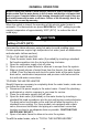
WARNING
Proper ground connection is essential. The presence of water in the
piping and water heater does NOT provide sufficient conduction for a
ground. Nonmetallic piping, dielectric unions, flexible connectors, etc.,
can cause the water heater to be electrically isolated. Do NOT
disconnect factory ground.