LIGHT DUTY/LIGHT SERVICE COMMERCIAL ELECTRIC WATER HEATER A Spanish language version of these instructions is available by contacting the company listed on the rating plate. La versión espãnola de estas instrucciones se puede obtener al escribirle a la fábrica cuyo nombre aparece en la placa de especificaciones.
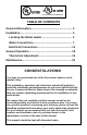
For Canadian Installations TABLE OF CONTENTS General Information ...................................................... 5 Installation...................................................................... 6 Locating the Water Heater ........................................ 6 Water Connections .................................................... 7 Electrical Connections .............................................. 13 General Operation .........................................................
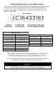
Determining the Age of Your Water Heater The first two characters of the serial number represent the year and month of manufacture. The remainder of the serial is a sequential production number, seven digits in length before December 2007 (DM), and eight digits in length after.
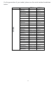
MODEL For the generation of your model, please see the serial number breakdown below: LE120L LE230LN LE240LN LE250LN GEN 1 --------- GEN 2 YG + YG + YG + YG + LE330S LE340S LE350S ------- YG + YG + YG + LE112T LE255T LE265T LE280T LE2120T ----YF to YG YF to YG YF to YG YG + YG + YG + YG + YG + LE16U LE120U LE220U ------- YG + YG + YG + SLE280T SLE2120T SLE265T YF to YG YF to YG YF to YG YG + YG + YG + 4
GENERAL INFORMATION This electric water heater’s design is certified by Underwriters Laboratories (UL) and listed in accordance with UL 1453 and cUL listed in accordance with Canadian National Standard C22.2, No. 110. This water heater must be installed in accordance with local codes. In the absence of local codes, install this water heater in accordance with the latest edition of National Electrical Code NFPA 70.
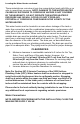
General Information continued- IMPORTANT Before proceeding, please inspect the water heater and its components for possible damage. DO NOT install any damaged components. If damage is evident, please contact the supplier where the water heater was purchased, or the manufacturer listed on the rating plate for replacement parts. INSTALLATION Locating The Water Heater WARNING Water heaters are heat producing appliances.
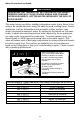
Locating the Water Heater continued- These materials are corrosive at very low concentration levels with little or no odor to reveal their presence. NOTE: DAMAGE TO THE WATER HEATER CAUSED BY EXPOSURE TO CORROSIVE VAPORS IS NOT COVERED BY THE WARRANTY. DO NOT OPERATE THE WATER HEATER IF EXPOSURE HAS OR WILL OCCUR. DO NOT STORE ANY POTENTIALLY CORROSIVE COMPOUNDS IN THE VICINITY OF THE WATER HEATER.
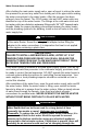
Water Connections continued- After shutting the main water supply valve, open a faucet to relieve the water line pressure to prevent any water from leaking out of the pipes while making the water connections to the water heater. After the pressure has been relieved, close the faucet. The COLD-water inlet and HOT-water outlet are identified on top of the water heater. The fittings at the cold-water inlet and hot water outlet are dielectric waterway fittings with 3/4” NPT tapered male threads.
pipe as the water begins to flow. There should be no smoking or open flame near the faucet at the time it is open.
Water Connections continued- CAUTION INCREASING THE THERMOSTAT SETTING ABOVE THE PRESET TEMPERATURE MAY CAUSE SEVERE BURNS AND CONSUME EXCESSIVE ENERGY. HOTTER WATER INCREASES THE RISK OF SCALD INJURY. This water heater can deliver scalding temperature water at any faucet in the system. Be careful whenever using hot water to avoid scalding injury. Certain appliances, such as dishwashers and automatic clothes washers, may require increased temperature water.
Water Connections continued- Upright Models (See Figure 1A & 1B) The hot and cold-water connections are identified on the top of the water heater (See figure 1A). For bottom inlet models, the cold-water inlet is located on the side of the drain valve (see figure 1B). Connect the hot and cold-water lines to the installed nipples using unions. Install a listed temperature-pressure relief valve in the remaining fitting.
Water Connections continued- Utility Models (See Figure 2) Utility models are supplied with inlet and outlet nipples located in a plastic bag attached to the side of the water heater. The hot and cold-water connections are identified on the side of the water heater. Apply appropriate amount of thread sealant to the provided nipples and install them into the side of the tank. For 20-gallon utility models, install the supplied anode/nipple combination at the HOT outlet location.
Electrical Connections Before any electrical connections are made, be sure that the water heater is full of water and that the manual shut-off valve in the cold-water supply line is open. Check the rating plate and wiring diagram before proceeding. This electric water heater was built and wired in accordance with the UL testing approvals requirements.
Electrical Connections continued- Figure 3A Figure 3B 14
Electrical Connections continued- Figure 4 15
Electrical Connections continued- The maximum wattage and rate voltage are shown on the water heater data plate. FOR YOUR SAFETY Increasing the wattage and/or voltage from the factory original equipment can require changes to the water heater and/or the electric service. Unauthorized modification of the water heater may create a hazard to life and property and will nullify the warranty. Contact your dealer or utility company before making any changes.
Electrical Connections continued- 17
GENERAL OPERATION Before closing the switch to allow electric current to flow to the water heater, make certain that the water heater is full of water and that the cold-water inlet valve is open. Complete failure of the heating element(s) will result if they are not totally immersed in water at all times. Failure of the element(s) due to dry firing is not covered by warranty. When the switch is closed, the operation of this electric water heater is automatic.
Thermostat Adjustment CAUTION Before adjusting thermostat(s), turn off power supply to the water heater. The temperature of the water can be changed by adjusting the thermostat(s). Before any work is done on the water heater, disconnect all power to the water heater by opening the switch at the main electrical circuit breaker or fuse box. Remove the access panels or front panel on tabletops, fold the insulation outward away from the controls.
MAINTENANCE IMPORTANT The water heater should be inspected at a minimum of annually by a qualified service technician for damaged components. DO NOT operate this water heater if any part is found damaged. Shut off the electric power whenever the water supply to the water heater is off. Shut off the electric power and water supply, drain the heater completely to prevent freezing whenever the building is left unoccupied during the cold weather months.
Maintenance continued- WARNING When lifting lever of temperature-pressure relief valve, hot water will be released under pressure. Be certain that any released water does not result in bodily injury or property damage. 4. If the combination temperature and pressure relief valve on the appliance discharges periodically, this may be due to thermal expansion in a closed water supply system. Contact the water supplier or local plumbing inspector on how to correct this situation.
Maintenance continued- Contact your local plumbing supplier or plumbing professional for replacement parts or contact the company at the address displayed on the rating plate of the water heater. For faster and better service, please provide the part name, model, and serial number(s) of the water heater(s) when ordering parts. READ THE WARRANTY FOR A FULL EXPLANATION OF THE LENGTH OF TIME THAT PARTS AND THE WATER HEATER ARE WARRANTED.
NOTES 23
NOTES 24