DOUBLE-WALL INDIRECT-FIRED WATER HEATER A Spanish language version of these instructions is available by contacting the manufacturer listed on the rating plate. La version espanola de estas instruccions se puede obtener al escribirle a la fábrica cuyo nombre aparece in la placa de especificaciones.
CONGRATULATIONS! You have just purchased one of the finest water heaters on the market today! This installation, operation, and instruction manual will explain in detail the installation and maintenance of your new Indirect water heater. We strongly recommend that you contact a plumbing professional for the installation of this water heater. We require that you carefully read this manual, as well as the enclosed warranty, and refer to it if questions arise.
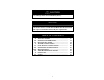
CAUTION The maximum boiler water supply temperature to the indirect heat exchanger must not exceed 240°F (115°C). NOTICE Insulation blankets are not required for this water heater. This water heater meets or exceeds the ASHRAE/IES 90.1b standards with respect to insulation and standby loss requirements. TABLE OF CONTENTS IIIIIIIVVVIVIIVIIIIXXXI- IMPORTANT INFORMATION…………….….. SPECIFICATIONS………………………………. GENERAL INFORMATION……………………. PRE-INSTALLATION…………………………… WATER CONNECTIONS………………………..
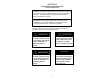
SECTION I IMPORTANT INFORMATION -READ CAREFULLYThe equipment must be installed in accordance with those installation regulations required in the area where the installation is to be made. These regulations must be carefully followed in all cases. Authorities having jurisdiction shall be consulted before installations are made.
Important Info continued- DANGER DO NOT store or use gasoline or other flammable, combustible, or corrosive vapors and/or liquids in the vicinity of this or any other appliance. IF YOU SMELL GAS: DO NOT try to light any appliance. DO NOT touch any electric switch; do not use any telephone in your building. Immediately call your gas supplier from a telephone in another building. Follow the gas supplier’s instructions.
Important Info continued- WARNING Installation is not complete unless a properly sized/capacity pressure and temperature relief valve is installed into the side of the water heater. See the General Information section of this manual for details. This water heater contains very hot water under high pressure. Do not unscrew any pipe fittings or attempt to disconnect any components of this water heater without positively assuring the water is cool and has no pressure.
Important Info continued- WARNING It is the responsibility of the installing contractor to see that all controls are correctly installed and are operating properly when the installation is complete. DO NOT operate the water heater with jumpered or absent controls or safety devices. DO NOT tamper with or alter the water heater and/or controls. DO NOT operate the water heater if any external part has been under water.
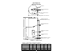
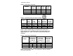
SECTION II SPECIFICATIONS ANODES COLD WATER OUTLET 3/4” NPT HOT WATER OUTLET 3/4” NPT WIRING JUNCTION BOX TEMPERATURE AND PRESSURE RELIEF VALVE FROM BOILER SUPPLY 3/4” NPT THERMOSTAT UNDER COVER TO BOILER RETURN 3/4” NPT DRAIN COUPLING- 3/4” NPT DRAIN VALVE – 5/8” NH Figure 1 – Tank Layout Table 1: Water Heater Dimension (Inches) MODEL 40-Gal. 50-Gal. 65-Gal. 80-Gal.
Specifications continued- Table 2: Water Heater Capacities Tank Coil Capacity Volume (Gal) (Gal) MODEL 40-Gal. 50-Gal. 65-Gal. 80-Gal. 38 46 60 75 Dry Weight (Lbs) Wet Weight (Lbs) 170 180 196 224 470 547 695 848 2.5 2.5 2.5 2.
Specifications continued- Table 5: Water Heater Performance MODEL 40-Gal. 50-Gal. 65-Gal. 80-Gal. Hot Water Coil Heat Availability Transfer Area (Minutes) (Sq Ft) 6.8 14.2 8.6 14.2 10.8 14.2 13.5 14.2 Pressure Drop at Rated Heat Source Flow Rate (Feet of Head) 2.4 2.4 2.4 2.4 NOTICE If the boiler takes longer to heat up from a cold start than the water availability as noted above, hot water shortage may occur.
SECTION III GENERAL INFORMATION FEATURES This water heater contains the following features: HEAT EXCHANGER -- The heat exchanger (coil) has 3/4” NPT female fittings. Water heaters with a double-wall heat exchanger meet the Uniform Plumbing Code for installation in all potable water systems. The doublewall construction provides protection in the event that either the potable or hydronic heat exchanger barrier is penetrated.
General Info continued- TEMPERATURE AND PRESSURE RELIEF VALVE WARNING Keep clear of the combination temperature and pressure relief valve discharge line outlet. The discharge may be hot enough to cause scald injury. The water is under pressure and may splash.
General Info continued- WARNING Install a discharge line so that water discharged from the temperature and pressure relief valve will exit within six (6) inches above, or any distance below, the structural floor and cannot contact any live electrical part. The discharge line is to be installed to allow for complete drainage of both the temperature and pressure relief valve and the discharge line. The discharge opening must not be subjected to blockage or freezing.
SECTION IV PRE-INSTALLATION UNPACKING INSPECT SHIPMENT carefully for any signs of damage. If damage is noted, do not install the product. Contact the shipper or manufacturer. All equipment is carefully manufactured, inspected, and packed. Our responsibility ceases upon delivery of the packaged water heater to the carrier in good condition. NOTE: Any claims for damage or shortage in shipment must be filed immediately against the carrier by the consignee.
Pre-installation continued- NOTICE Increasing the boiler DOE heating capacity above the values listed in Table 3 will not increase the rating of the water heater. 2. Circulator Sizing – Refer to Table 5 for the corresponding pressure drop through the coil for the given model. Calculate the pressure drop of all straight pipe and fittings on the supply and return of the water heater at the selected flow rate. Add the piping/fitting pressure drop to the pressure drop through the water heater coil.
Pre-installation continued- DOMESTIC HOT WATER PRIORITY Two options are available, Priority and Non-Priority. 1. Priority – Demand for space heating is interrupted or postponed until the domestic hot water demand is satisfied. This option provides maximum delivery of domestic hot water.
Pre-installation continued- Clearance from Combustible Materials Top 0” Sides 0” Front 0” Rear 0” Table 6 – Combustible Material Clearances Recommended Service Clearances Non-Piping Side Front (Thermostat ) 16” 4” Rear T & P Relief Valve Side 0” 4” Table 7 – Service Clearances CAUTION Do not drop water heater. Do not bump water heater jacket against floor. Appliance Location 1. Boiler Location – Locate the indirect-fired water heater as close to the boiler as practical. 2.
Pre-installation continued- MOVE THE WATER HEATER TO A PERMANENT POSITION BY SLIDING OR WALKING. NOTICE For California installation this water heater must be braced, anchored, or strapped to avoid falling or moving during an earthquake. See instructions for correct installation procedures. Instructions may be obtained from California Office of the State Architect, 400 P Street, Sacramento, CA 95814.
Water Connections continued- CAUTION If sweat fittings are to be used, DO NOT apply heat to the nipples on top of the water heater. Sweat the tubing to the adapter before fitting the adapter to the water connections. It is imperative that heat is not applied to the nipples containing a plastic liner. INSTALL TEMPERATURE AND PRESSURE RELIEF VALVE (if not factory installed) WARNING Temperature and pressure relief valve discharge piping must be piped near the floor to eliminate potential of severe burns.
Water Connections continued- plumbing inspector should be contacted on how to control this situation. 3. After installation of the water lines, open the main water supply valve and fill the water heater. While the water heater is filling, open several hot water faucets to allow air to escape from the water system. When steady streams of water flow through the faucets, close them and check all water connections for possible leaks. 4.
Water Connections continued- Figure 2 - Water Boiler Piping with Zone Valves 2. For a space heating system that utilizes CIRCULATORS, refer to Figure 3. The indirect-fired water heater connection labeled “FROM BOILER SUPPLY” should be piped to the boiler supply piping. Mount the circulator making sure the flow arrow points toward the water heater. The use of shut-off valves and unions are recommended for future service convenience.
Water Connections continued- CONNECT STEAM BOILER SUPPLY PIPING Figure 4 represents a typical steam boiler connection diagram. Refer to the boiler installation manual or contact the boiler manufacturer for an appropriate piping diagram. The use of a union, shut-off valves, and a drain valve is recommended for future service convenience. The use of an in-line “Y”-style strainer is required to prevent accumulation of sludge in the water heater’s coil.
SECTION VI ELECTRICAL CONNECTIONS Install electric wiring in accordance with National Electric Code or the Canadian Electrical Code and local regulations. See the boiler’s installation manual for wiring diagrams. DANGER Positively assure all electrical connections are unpowered before attempting installation or service of electrical components or connections of the water heater or building. Lock out all electrical boxes with padlock once power is turned off.
Electrical Connections continued- The thermostat switch is a single pole, single throw device. The field connections shall be used as a control for one leg of the electrical circuit. The thermostat switch can be used in the range of 24 to 480 volts with a maximum current load of 15 amps. Any and all wiring shall be sized and installed to satisfy the voltage and amperage used. All wiring shall be done in accordance with all applicable local and state codes.
Electrical Connections continued- If a zone valve to used to control the heating fluid flow from the boiler to the water heater, a zone step-down transformer is required between the water heater thermostat and the zone valve. Connect the white wire on the water heater to one leg of the transformer primary side. The second leg of the primary side is to be connected to “L2” (120V neutral). The secondary side of the transformer is to be connected to the zone valve coil.
SECTION VII OPERATING INSTRUCTIONS WARNING Water heaters are heat-producing appliances. To avoid damage or injury there must be no materials stored against the water heater, and proper care must be taken to avoid unnecessary contact (especially by children) with the water heater. UNDER NO CIRCUMSTANCES SHALL FLAMMABLE MATERIALS, SUCH AS GASOLINE OR PAINT THINNER BE USED OR STORED IN THE VICINITY OF THE WATER HEATER OR IN ANY LOCATION FROM WHICH FUMES COULD REACH THE WATER HEATER.
Operating Instructions continued- WATER TEMPERATURE ADJUSTMENT WARNING SCALDING This water heater can deliver scalding temperature water at any faucet in the system. Be careful whenever using hot water to avoid scalding injury. By setting the thermostat on this water heater to obtain an increased water temperature, you may create the potential for scald injury.
Operating Instructions continued- CAUTION Before adjusting the thermostat, turn off all power supplied to the indirect-fired water heater. The potable water temperature can be changed by adjusting the thermostat. Before any work is done on the water heater, disconnect all power to the water heater and heat source (boiler) by opening the switch(s) at the main electrical circuit breaker or fuse box. Remove the access panel and fold the insulation outward away from the control.
Operating Instructions continued- Adjusting to a lower temperature setting will not immediately affect water temperature. Draw sufficient water or allow the water heater to remain idle until a heat-up cycle is initiated. After the heater’s heat-up cycle is complete, check the water temperature at a faucet to determine if further adjustment is necessary. Adjusting to a higher temperature may not immediately affect water temperature.
Maintenance continued- CAUTION Before manually operating the valve, make sure that a drain line has been attached to the valve to direct the discharge to an open drain. Failure to take this precaution could mean contact with extremely hot water discharging from the valve during this checking operation.
Maintenance continued- To inspect or replace an anode: The anodes on this water heater are easily accessible from the top of the heater making replacement simple and quick. a. Turn the water heater electricity off for the zone containing the indirect-fired water heater. Flow water until the discharge is cool or allow enough time for the potable water to cool naturally. Connect a hose to the drain valve.
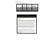
SECTION IX TROUBLESHOOTING GUIDE PROBLEM No hot water at faucet CAUSE Boiler does not operate Circulator does not operate Temperature high limit on thermostat tripped Improper thermostat setting or calibration Zone valve does not open (if used) Electrical problem (relay, wiring, etc.
Trouble Shooting Guide continued- PROBLEM CAUSE Insufficient hot water Thermostat setting too low Boiler cycles more than 5 times per day in summer Undersized boiler with no priority to domestic hot water Peak use of hot water is greater than tank storage capacity Faulty tank thermostat Excessive demand Faulty thermostat Boiler high limit set too low 34 SOLUTION Adjust thermostat to higher setting.
SECTION X PARTS LIST PART NAME & DESCRIPTION 1. Electrical Outlet Cover 2. Conduit Grounding Cover 3. Outlet Anode Device 4. Hole Closure 5. Hex Head Anode 6. Inlet Diptube 7. Escutcheon 8. T&P Relief Valve 9. Heat Exchanger Escutcheon 10. Thermostat Bracket 11. Access Cover 12. Drain Valve 13. Thermostat Protector 14.
Contact your supplier or plumbing professional for replacement parts or contact the company at the address given on the rating plate of the water heater. Provide the part name, model, and serial numbers of the water heater when ordering parts. READ THE WARRANTY FOR A FULL EXPLANATION OF THE LENGTH OF TIME THAT PARTS AND THE WATER HEATER ARE WARRANTED. Manufactured under one or more of the following U.S. Patents: RE.
NOTES 37