
Installation / Operation Instruction Manual
22
Electrical Connections continued-
The thermostat incorporates a manual reset temperature-limiting device.
Please refer to the TROUBLESHOOTING GUIDE section for manual
reset operation.
The thermostat incorporates a manual adjustable temperature indicator
to change the potable water temperature. Please refer to WATER
TEMPERATURE ADJUSTMENT in the OPERATING INSTRUCTIONS
section for proper instruction in adjusting water temperature. Turn OFF
all power related to the boiler and heating system before proceeding with
the electrical connections.
The thermostat switch is a single pole, single throw device. The field
connections shall be used as a control for one leg of the electrical circuit.
The thermostat switch can be used in the range of 24 to 480 volts with a
maximum current load of 15 amps. Any and all wiring shall be sized and
installed to satisfy the voltage and amperage used. All wiring shall be
done in accordance with all applicable local and state codes.
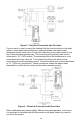
GENERAL INSTALLATIONS
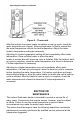
If a circulator is used to control the heating fluid flow from the water
heater to the boiler, a zone relay is required between the water heater
thermostat and the boiler. Connect the white wire on the water heater to
one leg of the circulator. The second leg of the circulator is to be
connected to “L2” (120V neutral). Connect the white wire on the water
heater to one leg of the zone relay. The second leg of the zone relay is
to be connected to “L2” (120V neutral). The contact side of the zone
relay is to be connected to the boiler operating control (see figure 5).
Connect the black wire on the water heater to “L1” (120V hot). These
connections enable water heater thermostat to control the circulator, the
zone relay, and the boiler operating control.