Double-Wall Indirect-Fired WATER HEATER A Spanish language version of these instructions is available by contacting the manufacturer listed on the rating plate. La version espanola de estas instruccions se puede obtener al escribirle a la fábrica cuyo nombre aparece in la placa de especificaciones.
CONGRATULATIONS! You have purchased one of the finest water heaters on the market today! This installation, operation, and instruction manual will explain in detail the installation and maintenance of your new Indirect water heater. We strongly recommend that you contact a plumbing professional for the installation of this water heater. We require that you carefully read this manual, as well as the enclosed warranty, and refer to it if questions arise.
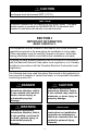
CAUTION The maximum boiler water supply temperature to the indirect heat exchanger must not exceed 240°F (115°C). NOTICE Insulation blankets are not required for this water heater. This water heater meets or exceeds the ASHRAE/IES 90.1b standards with respect to insulation and standby loss requirements. SECTION I IMPORTANT INFORMATION -READ CAREFULLYThe equipment must be installed in accordance with those installation regulations required in the area where the installation is to be made.
Important Information continued- DANGER DO NOT store or use gasoline or other flammable, combustible, or corrosive vapors and/or liquids in the vicinity of this or any other appliance. IF YOU SMELL GAS: • DO NOT try to light any appliance. • DO NOT touch any electric switch; DO NOT use any telephone in your building. • Immediately call your gas supplier from a telephone in another building. Follow the gas supplier’s instructions.
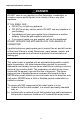
Important Information continued- WARNING Installation is not complete unless a properly sized/capacity pressure and temperature relief valve is installed into the side of the water heater. See the General Information section of this manual for details. This water heater contains very hot water under high pressure. DO NOT unscrew any pipe fittings or attempt to disconnect any components of this water heater without positively assuring the water is cool and has no pressure.
Important Information continued- WARNING It is the responsibility of the installing contractor to see that all controls are correctly installed and are operating properly when the installation is complete. DO NOT operate the water heater with jumpered or absent controls or safety devices. DO NOT tamper with or alter the water heater and/or controls. DO NOT operate the water heater if any external part has been under water.
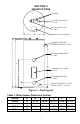
SECTION II SPECIFICATIONS ANODES COLD WATER OUTLET 3/4” NPT HOT WATER OUTLET 3/4” NPT WIRING JUNCTION BOX TEMPERATURE AND PRESSURE RELIEF VALVE FROM BOILER SUPPLY 3/4” NPT THERMOSTAT UNDER COVER TO BOILER RETURN 3/4” NPT DRAIN COUPLING- 3/4” NPT DRAIN VALVE – 5/8” NH Figure 1 – Tank Layout Table 1: Water Heater Dimension (Inches) Model A B C D E F 40-Gal. 50-Gal. 65-Gal. 80-Gal.
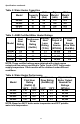
Specifications continued- Table 2: Water Heater Capacities Tank Coil Model Capacity Volume (Gal) (Gal) 40-Gal. 50-Gal. 65-Gal. 80-Gal. 37 43 57 71 Dry Weight (Lbs) Wet Weight (Lbs) 170 180 196 224 470 547 695 848 2.5 2.5 2.5 2.5 Table 3: AHRI Certified Water Heater Ratings Standby Minimum First Continuous Heat Output of Hour Draw Model Loss Heat Rating Rating Rating Source (Gal/Hr) (Gal/Hr) (°F/Hr) (BTU/Hr) 40-Gal 50-Gal 65-Gal 80-Gal 110 120 135 145 85 85 85 85 1.1 0.9 0.8 0.
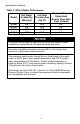
Specifications continued- Table 5: Water Heater Performance Model Hot Water Availability (Minutes) Coil Heat Transfer Area (Sq Ft) Pressure Drop at Rated Heat Source Flow Rate (Feet of Head) 40-Gal. 50-Gal. 65-Gal. 80-Gal. 6.8 8.6 10.8 13.5 14.2 14.2 14.2 14.2 2.4 2.4 2.4 2.4 NOTICE If the boiler takes longer to heat up from a cold start than the water availability as noted above, hot water shortage may occur.
SECTION III GENERAL INFORMATION FEATURES This water heater contains the following features: HEAT EXCHANGER – The heat exchanger (coil) has 3/4” NPT female fittings. Water heaters with a double-wall heat exchanger meet the Uniform Plumbing Code for installation in all potable water systems. The doublewall construction provides protection in the event that either the potable or hydronic heat exchanger barrier is penetrated.
General Information continued- TEMPERATURE AND PRESSURE RELIEF VALVE WARNING Keep clear of the combination temperature and pressure relief valve discharge line outlet. The discharge may be hot enough to cause scald injury. The water is under pressure and may splash.
General Information continued- WARNING Install a discharge line so that water discharged from the temperature and pressure relief valve will exit within six (6) inches above, or any distance below, the structural floor and cannot contact any live electrical part. The discharge line is to be installed to allow for complete drainage of both the temperature and pressure relief valve and the discharge line. The discharge opening must not be subjected to blockage or freezing.
Pre-installation continued- IMPORTANT DECISIONS REQUIRED BEFORE INSTALLATION SIZING 1. Boiler DOE Heating Capacity – The indirect-fired water heater will provide the rated performance only if used in conjunction with a heat source with a DOE heating capacity (Heat Output) at least as much as the minimum noted in Table 3. If the heat source has less capacity, the output of the tank will be reduced.
Pre-installation continued- SYSTEM ZONE CONTROL The indirect-fired water heater must be installed as a zone separate from the space heating system. The domestic hot water zone’s piping and circulator must be sized for a minimum flow rate with all zones in use and a maximum flow rate with only the water heater in use. For this reason, the preferred method of zone control is with circulators. 1.
Pre-installation continued- COMPONENT LOCATION CAUTION This water heater must be located in an area where leakage of the tank, water line connections, or the temperature and pressure relief valve will not result in damage to the area adjacent to the water heater or to lower floors of the structure. When such locations cannot be avoided, a suitable drain pan must be installed under the water heater. The drain pan depth must be suitable for draining and collecting water.
Pre-installation continued- ADDITIONAL RECOMMENDED COMPONENTS 1. Shut-off Valves – Allows isolation of water heater from domestic water system and/or boiler system during service. 2. Unions – Allows water heater movement during service if adequate clearance cannot be provided. 3. Thermal Expansion Tank – If the water heater is installed in a closed water supply system, such as one having a back-flow preventer in the cold water line, provide thermal expansion control.
SECTION V WATER CONNECTIONS WARNING FAILURE TO INSTALL AND MAINTAIN A NEW, LISTED TEMPERATURE AND PRESSURE RELIEF VALVE WILL RELEASE THE MANUFACTURER FROM ANY CLAIM WHICH MIGHT RESULT FROM EXCESSIVE TEMPERATURE AND PRESSURES. Hydrogen gas can be produced in an operating water heater that has not had water drawn from the tank for a long period of time. HYDROGEN GAS IS EXTREMELY FLAMMABLE.
Water Connections continued- INSTRUCTIONS FOR POTABLE CONNECTIONS 1. BEFORE PROCEEDING WITH THE INSTALLATION, CLOSE THE MAIN WATER SUPPLY VALVE. After shutting off the main water supply, open a faucet to relieve the water line pressure to prevent any water from leaking out of the pipes while making the water connections to the water heater. After the pressure has been relieved, close the faucet. The COLD water inlet and HOT water outlet are identified on the top of the water heater.
Water Connections continued- CONNECT WATER BOILER SUPPLY PIPING 1. For a space heating system that utilizes ZONE VALVES, refer to Figure 2. The indirect-fired water heater connection labeled “FROM BOILER SUPPLY” should be piped to the boiler supply piping. Mount the circulator making sure the flow arrow points toward the water heater. The use of shut-off valves and unions are recommended for future service convenience. The use of an air separator and vent is recommended to eliminate air in the system.
Water Connections continued- Figure 3 - Water Boiler Piping with Circulators CONNECT STEAM BOILER SUPPLY PIPING Figure 4 represents a typical steam boiler connection diagram. Refer to the boiler installation manual or contact the boiler manufacturer for an appropriate piping diagram. The use of a union, shut-off valves, and a drain valve is recommended for future service convenience. The use of an in-line “Y”-style strainer is required to prevent accumulation of sludge in the water heater’s coil.
Water Connections continued- NOTICE Typical steam boiler without connections available below the water line is not recommended due to insufficient water temperature, especially during warmer months when the space heating system is not operational. Boiler water temperature at the bottom of a steam boiler can be 50°F lower than the boiler’s water temperature limit setting during such periods. FILL BOILER SYSTEM 1.
Electrical Connections continued- The thermostat incorporates a manual reset temperature-limiting device. Please refer to the TROUBLESHOOTING GUIDE section for manual reset operation. The thermostat incorporates a manual adjustable temperature indicator to change the potable water temperature. Please refer to WATER TEMPERATURE ADJUSTMENT in the OPERATING INSTRUCTIONS section for proper instruction in adjusting water temperature.
Figure 5 – Electrical Connection with Circulator If a zone valve to used to control the heating fluid flow from the boiler to the water heater, a zone step-down transformer is required between the water heater thermostat and the zone valve. Connect the white wire on the water heater to one leg of the transformer primary side. The second leg of the primary side is to be connected to “L2” (120V neutral). The secondary side of the transformer is to be connected to the zone valve coil.
SECTION VII OPERATING INSTRUCTIONS WARNING Water heaters are heat-producing appliances. To avoid damage or injury there must be no materials stored against the water heater, and proper care must be taken to avoid unnecessary contact (especially by children) with the water heater. UNDER NO CIRCUMSTANCES SHALL FLAMMABLE MATERIALS, SUCH AS GASOLINE OR PAINT THINNER BE USED OR STORED IN THE VICINITY OF THE WATER HEATER OR IN ANY LOCATION FROM WHICH FUMES COULD REACH THE WATER HEATER.
Operating Instructions continued- Table 8 details the approximate relationship of water temperature and time with regard to scald injury and may be used as a guide in determining the safest water temperature for your applications.
Operating Instructions continued- Figure 8 – Thermostat After the indirect-fired water heater completes a heat-up cycle, check the water temperature at a faucet. Allow enough water to flow to ensure that the water temperature reflects the tank temperature. Adjust the water heater’s temperature setting as necessary. Adjusting to a lower temperature setting will not immediately affect water temperature. Draw sufficient water or allow the water heater to remain idle until a heat-up cycle is initiated.
Maintenance continued- 1. Boiler and Domestic Water Piping (Annual) – Check all piping for signs of leakage at joints, unions, and shut-off valves. Repair as needed. 2. Temperature-Pressure Relief Valve (Annual)- The temperaturepressure relief valve should be checked to ensure that it is in operating condition. To check the relief valve, lift the lever at the end of the valve several times. The valve should seat properly and operate freely.
Maintenance continued- 4. To inspect or replace an anode: The anodes on this water heater are easily accessible from the top of the heater making replacement simple and quick. a. Turn the water heater electricity off for the zone containing the indirect-fired water heater. Flow water until the discharge is cool or allow enough time for the potable water to cool naturally. Connect a hose to the drain valve.
SECTION IX TROUBLESHOOTING GUIDE PROBLEM CAUSE Circulator does not operate SOLUTION Refer to boiler installation instructions Check main service switch Check fused disconnect Check power supply Replace as necessary Temperature high limit on thermostat tripped Determine reason for trip. Depress red “RESET” button on thermostat Boiler does not operate Improper thermostat setting or calibration No hot water at faucet Zone valve does not open (if used) Electrical problem (relay, wiring, etc.
Troubleshooting Guide continued- PROBLEM Insufficient hot water Boiler cycles more than 5 times per day in summer CAUSE Thermostat setting too low Undersized boiler with no priority to domestic hot water Peak use of hot water is greater than tank storage capacity Faulty tank thermostat Excessive demand Faulty thermostat Boiler high limit set too low 30 SOLUTION Adjust thermostat to higher setting.
SECTION X PARTS LIST PART NAME & DESCRIPTION 1. Electrical Outlet Cover 2. Conduit Grounding Cover 3. Outlet Anode Device 4. Hole Closure 5. Hex Head Anode 6. Inlet Diptube 7. Escutcheon 8. T&P Relief Valve 9. Heat Exchanger Escutcheon 10. Thermostat Bracket 11. Access Cover 12. Drain Valve 13. Thermostat Protector 14.
Contact your supplier or plumbing professional for replacement parts or contact the company at the address given on the rating plate of the water heater. Provide the part name, model, and serial numbers of the water heater when ordering parts. READ THE WARRANTY FOR A FULL EXPLANATION OF THE LENGTH OF TIME THAT PARTS AND THE WATER HEATER ARE WARRANTED.