SUPPLEMENTAL INSTRUCTIONS FOR OPTIONAL VENT-AIR INTAKE KIT INSTALLATION VENTING INSTALLATION These instructions are for the installation of optional vent-air intake kit(s) for a Direct Vent Gas Water Heater. A Direct Vent Gas Water Heater uses all air for combustion from the outside atmosphere and all flue gases are discharged to the outside atmosphere. WARNING The vent-air intake system must be properly installed.
TABLE OF CONTENTS Page OPTIONAL VENT-AIR INTAKE SYSTEM INSTALLATIONS......... .............. 3 Table A (Vertical Extensions For Vent-Air Intake Systems) [40 Gallon (151.4 Liter) models] ............................................................... 3 Table A (Vertical Extensions For Vent-Air Intake Systems) [50 Gallon (189.3 Liter) models] ............................................................... 4 Table B (Horizontal Extensions For Vent-Air Intake Systems) [All Models] ..............................
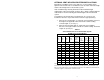
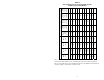
OPTIONAL VENT-AIR INTAKE SYSTEM INSTALLATIONS Each Direct Vent Water Heater comes with one (1) vent-air intake “Kit C.” Optional vent-air intake kits are available that can extend the horizontal length and/or vertical height of the vent-air intake system. Note: Additional kit(s) must be purchased for the horizontal length requirements of the vent-air intake system if “Kit C,” which is included with the water heater is used for extending the vertical height of the vent-air intake system.
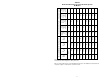
96 1/2 102 3/4 106 1/4 112 1/2 120 3/4 127 168 ½ 88 1/4 93 1/4 95 100 104 1/2 109 1/2 124 1/2 84 3/4 82 88 1/4 82 78 1/2 83 3/4 78 1/2 72 1/4 Max. (in.) 77 Min. (in.) 316.2 278.1 265.4 254 241.3 236.9 224.2 212.7 208.3 199.4 195.6 Min. (cm.) 12.1 428 322.6 306.7 285.8 269.9 261 245.1 224.2 215.3 208.3 199.4 Max. (cm.
29.2 37.5 49.5 54 66.7 78.7 92.1 14 3/4 24 30 1/4 33 3/4 38 3/4 48 1/4 53 1/4 14 3/4 19 1/2 21 1/4 26 1/4 31 36 1/4 24.1 11 9 1/2 11 1/2 16.5 Min. (cm.) 8 1/4 4-3/4 Max. (in.) 6 1/2 Min. (in.) 12.1 5 135.3 122.6 98.4 85.7 76.8 61 37.5 27.9 21 Max. (cm.) Horizontal Height “X” (See Figure 6) (2) (1) (1) (2) (1) (1) (1) (1) (1) (1) (1) (1) (1) (1) (1) (1) Kit C Part No. 32941029-00 (1) (1) (1) Kit B Part No.
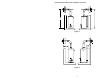
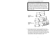
Optional Vent-Air Intake System Installations continued- Figure 1 Figure 2 6
Optional Vent-Air Intake System Installations continued- WARNING The vent-air intake system must be properly installed. Failure to properly install the vent-air intake system could result in property damage, personal injury or death. Do not install any damaged vent-air intake system components. Contact the manufacturer of the water heater for replacement parts.
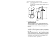
Optional Vent-Air Intake System Installations continued- IMPORTANT If your installation does not require optional vertical extension(s), then continue in this manual to the section titled “Installation of Horizontal Extensions” and follow the instructions. Installation of Vertical Extensions 1. If applicable, cut a 5-1/2 inch (13.6 cm) diameter minimum clearance hole in the ceiling where the telescopic vent-air intake tube(s) will pass through. (See Figure 3). Figure 3 2.
Optional Vent-Air Intake System Installations continued- Where: V = The required length of the three (3) inch (7.6 cm) diameter telescopic tube(s). Y = Height from the ground to the horizontal centerline of the ventair intake system. Figure 4 3. For a Single Telescopic Tube Adjust the length of the three (3) inch (7.6 cm) telescopic tube to dimension “V” calculated in the above formula. With a 1/8 inch drill bit (not supplied), drill three (3) holes, 120o apart, through the three (3) inch (7.
Optional Vent-Air Intake System Installations continued- IMPORTANT For ease of installation, it is recommended that none of the joint(s) in the vent-air intake system are located inside a ceiling. However, if a joint does end up inside a ceiling, conduct the following steps before installing the three (3) inch (7.6 cm) diameter telescopic tube(s) into the flue reducer. Drill three (3) 1/8 inch diameter holes, 120o apart, through the three (3) inch (7.
Optional Vent-Air Intake System Installations continued- Figure 6a Single Vertical Extension Kit Figure 6b Multiple Vertical Extension Kits 5. For a Single Telescopic Tube Compress the five (5) inch (12.7 cm) diameter telescopic tube to minimum length. Place the large end of the five (5) inch (12.7 cm) diameter telescopic tube through the hole in the ceiling (if applicable). Insert the small end of the five (5) inch (12.7 cm) diameter telescopic tube over the three (3) inch (7.
Optional Vent-Air Intake System Installations continued- For Multiple Telescopic Tubes Join the five (5) inch (12.7 cm) diameter telescopic tubes by inserting the small end of a tube into the large end of another, one (1) inch (2.5 cm) (or until seated). Drill three (3) 1/8 inch diameter holes, 120o apart, through each joint where the five (5) inch (12.7 cm) diameter telescopic tubes are joined. At this time, DO NOT drill holes where the small and large sections of the five (5) inch (12.
Optional Vent-Air Intake System Installations continued- 6. Extend the five (5) inch (12.7 cm) diameter telescopic tube(s) until it is one (1) inch (2.5 cm) below the top of the three (3) inch (7.6 cm) diameter telescopic tube(s). Drill three (3) 1/8 inch diameter holes, 120o apart, through the five (5) inch (12.7 cm) diameter telescopic tube(s) at the joint(s) where the small and large sections overlap. Fasten with three (3) #8 sheet metal screws (supplied). (See Figure 8a or 8b).
Optional Vent-Air Intake System Installations continued- Figure 8a Single Vertical Extension Kit Figure 8b Multiple Vertical Extension Kits 7. Insert the straight end of the three (3) inch (7.6 cm) diameter elbow one (1) inch (2.5 cm) (or until seated), into the end of the three (3) inch (7.6 cm) diameter telescopic tube(s). Make sure the three (3) inch (7.6 cm) diameter elbow is oriented in the correct direction. Drill three (3) 1/8 inch diameter holes, 120o apart, through the three (3) inch (7.
Optional Vent-Air Intake System Installations continued- Figure 9 8. Place the straight end of the five (5) inch (12.7 cm) diameter elbow over the three (3) inch (7.6 cm) diameter elbow into the end of the five (5) inch (12.7 cm) diameter telescopic tube(s), one (1) inch (2.5 cm) (or until seated). Make certain that the five (5) inch (12.7 cm) diameter elbow is oriented in the same direction as the three (3) inch (7.6 cm) diameter elbow and both are oriented in the correct direction.
Installation of Horizontal Extensions 1. Cut a 5-1/2 inch (13.6 cm) diameter minimum clearance hole in the wall at the point where the vent-air intake tubes will pass through the outside wall and connect with the direct vent-air intake terminal. (See Figure 11). Figure 11 2. From outside the building, position the outer wall mount plate and direct vent-air intake terminal over the center of the opening. Mark the mounting screw hole locations.
Optional Vent-Air Intake System Installations continued- 3. For water heaters where the three (3) inch (7.6 cm) diameter elbow is not yet installed: Insert the straight end of the three (3) inch (7.6 cm) diameter elbow into the flue reducer until firmly seated and oriented in the correct direction. With a 1/8 inch diameter drill bit (not supplied), drill three (3) holes, 120o apart, through the flue reducer into the three (3) inch (7.6 cm) diameter elbow.
Optional Vent-Air Intake System Installations continued- 5. For a Single Telescopic Tube Extend the three (3) inch (7.6 cm) diameter telescopic tube to its maximum length and slide the backing plate over it. Place the large end of the three (3) inch (7.6 cm) diameter telescopic tube through the hole in the outside wall. Insert the smaller end of the three (3) inch diameter (7.6 cm) telescopic tube into the flared end of the three (3) inch (7.6 cm) diameter elbow, one (1) inch (2.5 cm) (or until seated).
Optional Vent-Air Intake System Installations continued- IMPORTANT For ease of installation, it is recommended that none of the joint(s) in the vent-air intake system are located inside a wall. However, if a joint does end up inside a wall, conduct the following steps before installing the three (3) inch (7.6 cm) diameter telescopic tube(s) into the flared end of the three (3) inch (7.6 cm) diameter elbow. Drill three (3) 1/8 inch diameter holes, 120o apart, through the three (3) inch (7.
Optional Vent-Air Intake System Installations continued- Figure 15c 6. For a Single Telescopic Tube Extend the five (5) inch (12.7 cm) diameter telescopic tube to its maximum length. Place the large end of the five (5) inch (12.7 cm) diameter telescopic tube over the collar on the outer wall mount plate. Drill three (3) 1/8 inch diameter holes, 120o apart, through the five (5) inch (12.7 cm) diameter telescopic tube into the collar on the outer wall mount plate.
Optional Vent-Air Intake System Installations continued- IMPORTANT For ease of installation, it is recommended that none of the joint(s) in the vent-air intake system are located inside a wall. However, if a joint does end up inside a wall, conduct the following steps before installing the five (5) inch (12.7 cm) diameter telescopic tube(s) into the flared end of the five (5) inch (12.7 cm) diameter elbow. Drill three (3) 1/8 inch diameter holes, 120o apart, through the five (5) inch (12.
Optional Vent-Air Intake System Installations continued- 8. Using the supplied RTV silicone sealant, apply a bead one (1) inch (2.5 cm) from the end of the three (3) inch (7.6 cm) diameter tube that is part of the vent-air intake terminal. Slide the direct vent-air intake terminal into the three (3) inch (7.6 cm) diameter telescopic tube that extends through the wall and position it so it is flush with the outer wall mount plate.
Optional Vent-Air Intake System Installations continued- Figure 19 10. Mark the mounting screw hole locations for the backing plate. Rotate the backing plate in order to gain access to the markings. With a 3/16 inch diameter drill bit (not supplied), drill holes for the supplied wall anchors. Install the wall anchors and secure the backing plate to the wall with four (4) #10 x 1 inch screws (supplied). (See Figure 20).
Optional Vent-Air Intake System Installations continued- IMPORTANT When the installation is complete, visually inspect the air intake system to insure that all joints are completely sealed. WARNING THIS INSTRUCTION MANUAL IS ONLY A SUPPLEMENT TO THE INSTALLATION & OPERATING INSTRUCTION MANUAL SUPPLIED WITH THE WATER HEATER. REFER TO THE INSTALLATION & OPERATING INSTRUCTIONS SUPPLIED WITH THE WATER HEATER FOR COMPLETE INSTALLATION AND OPERATING PROCEDURES.