
Installation / Operation Instruction Manual

10
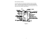
Electrical Connections
Before any electrical connections are made, be sure that the water heater is
full of water and that the valve in the cold water supply line is open. Check
the rating plate and wiring diagram before proceeding. This electric water
heater was built and wired in accordance with the Underwriters Laboratories
testing approvals requirements. The temperature limiting device is of the
manual reset, trip-free type and has been factory installed to interrupt all
ungrounded power supply conductors in the event of thermostat failure.
Thermostats are factory set and wired in accordance with the wiring diagram
fastened to the inside of the top access panel. The dealer in your area
ordered this heater wired at the factory to comply with existing area codes,
but local utility codes may require or allow other circuitry. Consult your local
power company to determine the correct electrical hook-up in order to meet
local utility and building codes and in order to obtain the most economical
rates. Also check to find out if you are required to obtain a permit before
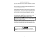
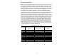
starting the installation. The following chart shows the recommended fuse
size for the maximum water heater wattage. The maximum wattage and
rated voltage are shown on the water heater data plate. The water heater
must be well grounded. A green ground screw is provided at the electrical
connection point for connecting a ground wire.
BRANCH CIRCUIT SIZING GUIDE
WATT
LOAD
RECOMMENDED OVER
CURRENT PROTECTION
RATING
COPPER WIRE SIZE - AWG
BASED ON N.E.C. TABLE
310-16 (60°C)
APPROXIMATE
RECOVERY GAL. PER
HOUR
@100°F RISE
120V 208V 240V 120V 208V 240V
1500 15A 15A 15A 12 14 14 6.1
2000 20A 15A 15A 10 14 14 8.2
2500 30A 15A 15A 10 14 14 10.2
3000 30A 20A 15A 8 12 12 12.3
3500 20A 20A 10 12 14.3
4000 25A 20A 10 10 16.3
4500 30A 25A 10 10 18.4
5000 30A 30A 10 10 20.5
5500 35A 30A 8 10 22.5
6000 35A 30A 8 8 24.8
9000 50A 45A 8 6 36.9
10000 60A 55A 4 4 41.0
11000 60A 4 45.1