
Install Instructions

4
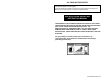
MINIMUM CLEARANCES
This water heater shall be installed on NON-COMBUSTIBLE flooring only. This
water heater may be installed in an alcove. Refer to the marking on the front of
the water heater for clearances to combustible materials.
The installation should allow access to the front of the water heater and adequate
clearance should be provided for servicing and operating the water heater. It is
recommended that a minimum clearance of 3” be provided on the side of the
water heater for servicing and maintenance of the temperature and pressure relief
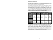
valve. If the rating plate or the label on the front of the water heater specifies
minimum clearances less than those listed in the below table, the water
heater should be installed in accordance with the minimum clearances listed
on the rating plate or the label on the front of the water heater.
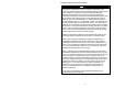
MINIMUM CLEARANCES TO COMBUSTIBLE MATERIALS
MODEL REAR SIDES FRONT
VENT
PIPE
ABOVE
CF-32
6”
(15.2cm)
6”
(15.2cm)
24”
(60.9cm)
9”
(22.8cm)
18”
(45.7cm)
CF-50
CF-70
CF-38
CF-80
CF-100
CDW170L
RF-30
18”
(45.7cm)
6”
(15.2cm)
24”
(60.9cm)
9”
(22.8cm)
6”
(15.2cm)
RF-30SX
RF-50
RF-70
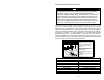
This water heater must be located in an area where leakage of the tank or water
line connections will not result in damage to the area adjacent to the water heater
or to lower floors of the structure. When such locations cannot be avoided, a
suitable drain pan must be installed under the water heater. The drain pan must
have a minimum length and width of at least 4 in. (10.2 cm) greater than the
diameter of the water heater and must not restrict proper combustion air flow to
the water heater. The drain pan, as described above, can be purchased from your
plumbing professional. The piping must be at least ¾” in diameter and pitched for
proper drainage. The pan must not restrict the combustion airflow.