
Install Instructions


14
Oil tanks and Piping Continued-
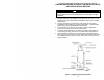
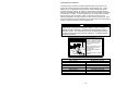
Fuel supply LEVEL with or ABOVE burner
The burner may be equipped with a single-stage fuel unit for these installations.
Connect the fuel supply to the burner with a single supply line if you want a 1-
pipe system (making sure the bypass plug is NOT installed in the fuel unit).
Manual bleeding of the fuel unit is required on initial start-up. If connecting a 2-
pipe fuel supply, install the fuel unit bypass plug.
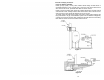
Fuel supply BELOW the level of the burner
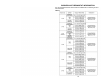
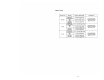
When the fuel supply is more than (8) feet below the level of the burner, a 2-pipe
fuel supply system is required. Depending on the fuel line diameter and horizontal
and vertical length, the installation may also require a 2-stage pump. Consult the
fuel unit manufacturer’s literature, included with the burner, for lift and vacuum
capability.
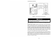
Fuel line installation
Continuous lengths of heavy wall copper tubing are recommended. Always use
flare fittings. Never use compression fittings.
Always install fittings in accessible locations. Proper routing of fuel lines is
required to prevent air cavitation and vibration.
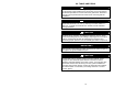
WARNING
DO NOT install by-pass plug with 1-pipe system. Failure to comply
could cause immediate pump seal failure, pressurized oil leakage and
the potential for a fire and injury hazard. The burner is shipped without
the by-pass plug installed. Install the by-pass plug in 2-pipe oil supply
systems ONLY.
CAUTION
Oil supply pressure control is required. Damage to the filter or pump
seals could cause oil leakage and a fire hazard. The oil supply inlet
pressure to the burner CANNOT exceed 3 psi. Insure that a pressure
limiting device is installed in accordance with the latest edition of NFPA
31.
DO NOT install valves in the return line (refer to NFPA 31).
For gravity feed systems, always install an anti-siphon valve in the oil
supply line or a solenoid valve in the pump/nozzle discharge tubing to
provide backup oil flow cut-off protection.