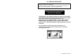
OIL-FIRED WATER HEATER A Spanish language version of these instructions is available by contacting the manufacturer listed on the rating plate. La version Espanola de estas instrucctions se puede obtener al escribirle a la fábrica cuyo nombre aparece in la placa de especificaciones. INSTALLATION & OPERATING INSTRUCTION MANUAL THE WARRANTY ON THIS WATER HEATER IS IN EFFECT ONLY WHEN THE WATER HEATER IS INSTALLED AND OPERATED IN ACCORDANCE WITH LOCAL CODES AND THESE INSTRUCTIONS.
TABLE OF CONTENTS General Information .................................................................................. 3 Installation ................................................................................................. 3 Locating the water heater .................................................................. 3 Minimum clearances .......................................................................... 4 Combustion air supply ...............................................................
GENERAL INFORMATION Note: It is recommended that the installation and service of this water heater be performed by a plumbing professional. This water heater must be installed in accordance with local codes. In the absence of local codes, it must be installed in compliance with the National Fire Protection Standard For Oil Burning Equipment NFPA No. 31 (latest edition).
MINIMUM CLEARANCES This water heater shall be installed on NON-COMBUSTIBLE flooring only. This water heater may be installed in an alcove. Refer to the marking on the front of the water heater for clearances to combustible materials. The installation should allow access to the front of the water heater and adequate clearance should be provided for servicing and operating the water heater.
WARNING Water heaters are heat-producing appliances. To avoid damage or injury, there shall be no materials stored against the water heater. Proper care shall be taken to avoid unnecessary contact (especially by children) with the water heater. UNDER NO CIRCUMSTANCES SHALL FLAMMABLE MATERIALS, SUCH AS GASOLINE OR PAINT THINNER, BE USED OR STORED IN THE VICINITY OF THIS WATER HEATER OR IN ANY LOCATION FROM WHICH FUMES COULD REACH THE WATER HEATER.
COMBUSTION AIR SUPPLY Installation of this water heater requires that provisions be made to supply adequate air for combustion and ventilation. If the building is unusually tight or if this water heater is installed in a small room, provisions for additional makeup air must be provided. This air must be supplied through two permanent openings located so that the lower edge of the lower opening is 6 inches below the top of the enclosure.
VENTING The connection from the water heater vent to the stack must be made as direct as possible and of the same diameter as the vent outlet. The recommended slope of any horizontal breaching is at least 1/2" rise per linear foot. A certified draft regulator (barometric damper) shall be installed in the venting with a location at least 18” downstream from the water heater. This water heater is designed for use with type “L” venting.
WATER CONNECTIONS Note: BEFORE PROCEEDING WITH THE INSTALLATION, CLOSE THE MAIN WATER SUPPLY VALVE. After shutting off the main water supply, open a faucet to relieve the water line pressure to prevent any water from leaking out of the pipes while making the water connections to the water heater. After the pressure has been relieved, close the faucet. The COLD water inlet and HOT water outlet are identified on the top of the water heater.
Installation (Water Connections) continued- WARNING For protection against excessive temperatures and pressure, install temperature and pressure protective equipment required by local codes, but not less than a combination temperature and pressure relief valve certified by a nationally recognized testing laboratory that maintains periodic inspection of production of listed equipment or materials as meeting the requirements of the Standard for Relief Valves and Automatic Gas Shutoff Devices for Hot Water Su
Installation (Water Connections) continued- WARNING Hydrogen gas can be produced in an operating water heater that has not had water drawn from the tank for a long period of time (generally two weeks or more). Hydrogen gas is extremely flammable. To prevent the possibility of injury under these conditions, we recommend the hot water faucet to be open for several minutes at the kitchen sink before you use any electrical appliance, which is connected to the hot water system.
THE FOLLOWING INSTRUCTIONS ARE FOR INSTALLATION OF: GAS WATER HEATERS SUITABLE FOR WATER (POTABLE) HEATING AND SPACE HEATING CAUTION If your water heater is equipped with an internal double wall coil, refer to the supplemental instructions supplied with this water heater for proper installation. 1. 2. 3. 4. 5. All water heaters are to be installed in accordance with local codes or, in the absence of such, with CAN/CSA-B214 Installation code for hydronic heating (latest edition).
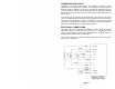
OIL TANKS AND PIPING CAUTION The instructions in this section are general guidelines. The instructions for the specific pump installed on the burner that you have purchased should take precedence over the instructions given below. Read all of the instructions provided with the burner before continuing with the installation. WARNING To prevent an oil leak and/or fire hazard, install the oil tank following applicable standards in the U.S.
Oil tanks and Piping Continued- Fuel Line Valves and Filter Install (2) high quality, oil duty rated, fusible handle design shutoff valves in accessible locations on the oil supply line. Locate one close to the tank and the other close to the burner, upstream of the filter for service access. Install a generous capacity filter inside the building between the fuel tank shutoff valve and the burner, locating both the filter and the valve close to the burner for ease of servicing.
Oil tanks and Piping Continued- Fuel supply LEVEL with or ABOVE burner WARNING DO NOT install by-pass plug with 1-pipe system. Failure to comply could cause immediate pump seal failure, pressurized oil leakage and the potential for a fire and injury hazard. The burner is shipped without the by-pass plug installed. Install the by-pass plug in 2-pipe oil supply systems ONLY. CAUTION Oil supply pressure control is required. Damage to the filter or pump seals could cause oil leakage and a fire hazard.
OPERATION TO FILL THE WATER HEATER 1. 2. 3. 4. Close the water heater drain valve by turning the handle clockwise. Open the cold water shut-off valve. Open several hot water faucets to allow air to escape from the system. When a steady stream of water flows at the hot water faucets, the water heater is filled. Close the faucets and check for water leaks at the temperature-pressure relief valve and the hot and cold water connections.
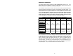
BURNER AND THERMOSTAT INFORMATION It is recommended that this water heater be installed with the following burners and thermostat: Table 1 16
Table 1 cont.
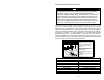
T’stat information Continued- The correct burners and thermostat may be purchased from the same supplier that provided the water heater to you. Installing the Burner: It is recommended that the burner be installed so that the face of the burner head is between 1/8” to 5/8” from the sides of the inside wall of the combustion chamber (see Figure 5). Note the top and bottom distances may vary slightly due to the curvature of the combustion chamber.
T’stat information Continued- This water heater can deliver scalding temperature water at any faucet in the system. Be careful whenever using hot water to avoid scalding injury. Certain appliances such as dishwashers and automatic clothes washers may require increased temperature water. By setting the thermostat on this water heater to obtain the increased temperature water required by these appliances, the potential for scald injury increases.
T’stat information Continued- Figure 6 – Thermostats with cover removed WARNING Escaping flue gases can be lethal. Make sure that the flue and venting system is checked at least once a year by a plumbing professional or the oil supplier's service technicians. Motor Lubrication: Oil motor with one or two drops of non-detergent motor oil. Priming The Fuel Units: Locate the air bleed valve on the fuel unit (pump). Place a container underneath the air bleed valve.
T’stat Information Continued- WARNING DO NOT ATTEMPT TO START THE BURNER WHEN EXCESS OIL HAS ACCUMULATED, WHEN THE UNIT IS FULL OF VAPOR, OR WHEN THE COMBUSTION CHAMBER IS HOT. TUNE-UP PROCEDURE A. To Put The Burner in Operation: Remove the temporary oil connection previously used and install a pressure gauge. Set all the controls to the normal starting position. Close the main cut out switch. The burner should start, ignite and burn.
T’stat information Continued- WARNING Draft reading in the stack should be -.02” W.C. to -.05” W.C. High draft may be caused by over firing, or too much excess air. If there is back draft caused by down draft, DO NOT operate the burner until this situation is corrected. Back pressure (back draft or down draft) may also be caused by the chimney termination being lower in elevation than surrounding objects, such as buildings, hills, trees, rooftops, etc.
MAINTENANCE In addition, the following steps should be performed at six-month intervals unless otherwise specified: 1. Make sure you clear the combustion air openings of any dust, lint or other restrictions. Flow of combustion air MUST NOT be restricted. 2. Check the burner flame periodically. If it becomes out of shape or smoky, call your service technician. 3. When cleaning your heater room or utility room, always turn off the burner to reduce the amount of dust and lint drawn into the burner. 4.
Maintenance Continued- Contact your supplier or plumbing professional for replacement parts or contact the company at the address given on the rating plate of the water heater. Provide the part name, model and serial numbers of the water heater when ordering parts. READ THE WARRANTY FOR A FULL EXPLANATION OF THE LENGTH OF TIME THAT PARTS AND THE WATER HEATER ARE WARRANTED. Manufactured under one or more of the following U.S. Patents: RE.