
Installation / Operation Instruction Manual

19
Venting (Part II) continued-
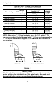
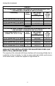
TABLE 6
VENT CONNECTOR LENGTHS FOR 3” (7.6 cm) DIAMETER VENT PIPE
Terminating
# of 90 Elbows
(excluding vent
terminal)
Max straight
Length
ft (m)
Min straight
Length
ft (m)
Through the Wall
1
115 (35)
10 (3.1)
Through the Wall
2
110 (33.5)
10 (3.1)
Through the Wall
3
105 (32.0)
10 (3.1)
Through the Wall
4
100 (30.5)
10 (3.1)
Through the Wall
5
95 (29.0)
10 (3.1)
Through the Roof
0
120 (36.6)
15 (4.6)
Through the Roof
1
115 (35)
15 (4.6)
Through the Roof
2
110 (33.5)
15 (4.6)
Through the Roof
3
105 (32.0)
15 (4.6)
Through the Roof
4
100 (30.5)
15 (4.6)
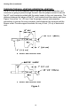
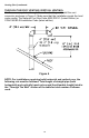
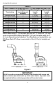
NOTE: When using 3” (7.6 cm) vent pipe, use a 3” (7.6 cm) to 2” (5.1 cm)
reducer and exit the building wall with 2” (5.1 cm) vent pipe using the 2”
(5.1 cm) 45 vent terminal supplied. Two 45 elbows are equivalent to one
90 elbow. Each 90° elbow is equivalent to 5 feet (1.5 m) of straight vent
pipe.
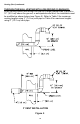
CONNECTION TO 2” (5.1 CM)
VENT PIPE
CONNECTION TO 3” (7.6 CM)
VENT PIPE
Figure 6
IMPORTANT
All of the venting connections must be leak checked with a soap and
water solution upon initial start up of the water heater. Any leaks must
be repaired before continuing operation of the water heater.