POWER VENT GAS WATER HEATER A Spanish language version of these instructions is available by contacting the company listed on the rating plate. La version espanola de estas instrucciones se puede obtener al escribirle a la fabrica cuyo nombre aparece en la placa de especificaciones. INSTALLATION AND OPERATION INSTRUCTION MANUAL WARNING: If the information in these instructions is not followed exactly, a fire or explosion may result causing property damage, personal injury, or death.
CONGRATULATIONS! You have purchased one of the finest water heaters on the market today! This installation, operation and instruction manual will explain in detail the installation and maintenance of your new Power Vented Gas Water Heater. We strongly recommend that you contact a plumbing professional for the installation of this water heater. We require that you carefully read this manual, as well as the enclosed warranty, and refer to it when questions arise.
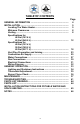
TABLE OF CONTENTS Page GENERAL INFORMATION ................................................................. INSTALLATION. .................................................................................. Locating The Water Heater.......................................................... Minimum Clearances ................................................................... Venting .......................................................................................... Specifications for 48 Gal (181.
GENERAL INFORMATION This gas-fired water heater’s design is certified by CSA International under the American National Standard Z21.10.1 and CSA 4.1-M, most current editions at the time of manufacture. This is a category III water heater. This water heater must be installed in accordance with local codes or, in the absence of local codes, the National Fuel Gas Code, ANSI Z223.1-Latest Edition) and/or in Canada CAN/CGA B149 Installation Codes (Latest Editions).
General Information continued- Make sure that you check the rating plate and combination gas control on the water heater to be certain that the type of gas being supplied corresponds with the marking on the rating plate and combination gas control. A sacrificial anode(s) is used to extend tank life. Removal of any anode, except for inspection and/or replacement, will nullify the warranty.
Installation (Locating The Water Heater) continued- The location of this water heater is of the utmost importance. Before installing this water heater, read the installation section of these instructions. After reading these installation and operating instructions, select a location for the water heater where the floor is level and is easily accessible to gas and water supply lines. DO NOT locate the water heater where water lines could be subjected to freezing temperatures.
Installation (Locating The Water Heater) continued- WARNING DO NOT ATTEMPT TO LIGHT ANY GAS APPLIANCE IF YOU ARE NOT CERTAIN OF THE FOLLOWING: • Liquefied petroleum gases/propane gas and natural gas have an odorant added by the gas supplier that aids in the detection of the gas. • Most people recognize this odor as a “sulfur” or “rotten egg” smell. • Other conditions, such as “odorant fade” can cause the odorant to diminish in intensity, or “fade”, and not be as readily detectable.
Minimum Clearances WARNING Failure to adhere to these installation and operating instructions may create a hazard to life and property and will nullify the warranty. This installation must allow access to the front of the water heater and adequate clearance must be provided for servicing and operating this water heater. The water heater may be installed on either a combustible or noncombustible floor.
Canadian Installations1 A= Clearance above grade, veranda, porch, deck or balcony 12 inches (30 cm) 6 in (15cm) for appliances ≤10,000 Btuh (3kW); 12 in (30 cm) for appliances >10,000 Btuh (3kW) and ≤100,000 Btuh (30kW); 36 in (91 cm) for appliances >100,000 Btuh (30 kW) US Installations2 12 inches (30 cm) 4 feet (1.
4. The vent shall terminate a minimum of 12” (25.4 cm) above expected snowfall level to prevent blockage of vent termination. Vent pipes serving power vented appliances are classified by building codes as “vent connectors”. Required clearances from combustible materials must be provided in accordance with information in this manual under “Locating the Water Heater” and “Minimum Clearances”, and with National Fuel Gas Code and local codes.
Venting continued- Approved Venting Materials For installations in the US only For installations in CANADA PVC DWV (ASTM D-2665) PVC Sch. 40, 80, 120 (ASTM-D1785) CPVC Sch. 40, 80 (ASTM-F441) CPVC (ASTM D2846) • ABS Sch.
Venting continued- Part I - Venting Specifications for: 48 Gallon (181.6 L) 65 Gallon (246.0 L) This water heater is a power vented appliance and is designed to vent its products of combustion through 3” (7.6 cm) or 4” (10.2 cm) diameter vent pipe to the outdoors. This water heater may be either vented horizontally through the wall or vertically through the roof. Use a 3” (7.6 cm) to 4” (10.2 cm) reducer to connect to the vent outlet when using 4” (10.2 cm) vent pipe.
Venting (Part I) continued- TABLE 2 -VENT CONNECTOR LENGTHS FOR 4” (10.2 cm) DIAMETER VENT PIPE Maximum straight # of 90 Length ft (m) Terminating Elbows (excl. vent term.) 48, 65 gal. Through the Wall Through the Wall Through the Wall Through the Wall Through the Wall Through the Roof Through the Roof Through the Roof Through the Roof Through the Roof 1 2 3 4 5 0 1 2 3 4 175 (53.3) 170 (51.8) 165 (50.3) 160 (48.8) 155 (47.2) 180 (54.9) 175 (53.3) 170 (51.8) 165 (50.3) 160 (48.
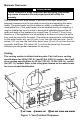
Venting (Part I) continued- THROUGH THE WALL VENTING (HORIZONTAL VENTING): Cut a 3 1/2 in. (8.9 cm) diameter hole in the wall at the point where the vent connector is going to pass through the wall. Use the proper cement to secure the 90° vent terminal provided with the water heater to the vent connector. The distance between the edges of the 90° vent terminal and the exterior wall (see Figure 3) must be 1 in. (2.5 cm).
Venting (Part I) continued- THROUGH THE ROOF VENTING (VERTICAL VENTING): Cut the necessary holes through the roof and ceiling and install the vent connector as shown in Figure 4. Make sure that the installation meets the local codes and/or The National Fuel Gas Code ANSI Z223.1 (Latest Edition) or CGA/CAN B149 Installation Code (latest edition).
Venting (Part I) continued- THROUGH THE WALL VENTING WITH LOW GROUND CLEARANCE: When venting cannot exit through the wall at a height greater than or equal to 12” (30.5 cm) above the ground, or anticipated snow level, the installation must be modified as shown below (see Figure 5). Refer to Table 3 for maximum venting lengths using 3” (7.6 cm) vent pipe or Table 4 for maximum lengths using 4” (10.2 cm) vent pipe.
Venting (Part I) continued- TABLE 3 3” (7.6 cm) VENT CONNECTOR LENGTHS FROM INSIDE WALL FOR LOW GROUND CLEARANCE INSTALLATIONS Terminating # of Max Straight Min Elbows Length ft (m) straight Length 48,65 gal. ft (m) 1 40 (12.2) 5 (1.5) (2) 90 Elbows with (1) 90 Elbow 2 35 (10.7) 5 (1.5) (2) 90 Elbows with (1) 90 Elbow 3 30 (9.1) 5 (1.5) (2) 90 Elbows with (1) 90 Elbow 4 25 (7.6) 5 (1.5) (2) 90 Elbows with (1) 90 Elbow TABLE 4 4” (10.
Venting continued- Part II - Venting Specifications for: 40 Gallon (151.4 L) 50 Gallon (189.2 L) 60 Gallon (227.1 L) This water heater is a power vented appliance and is designed to vent its products of combustion through 2” (5.1 cm) or 3” (7.6 cm) diameter vent pipe to the outdoors. The water heater may be either vented horizontally through the wall or vertically through the roof. Use a 3” (7.6 cm) to 2” (5.1 cm) reducer to connect to the vent outlet when using 3” (7.6 cm) vent pipe.
Venting (Part II) continued- TABLE 6 VENT CONNECTOR LENGTHS FOR 3” (7.6 cm) DIAMETER VENT PIPE Max straight Min straight # of 90 Elbows Terminating Length Length (excluding vent ft (m) ft (m) terminal) Through the Wall 1 115 (35) 10 (3.1) Through the Wall 2 110 (33.5) 10 (3.1) Through the Wall 3 105 (32.0) 10 (3.1) Through the Wall 4 100 (30.5) 10 (3.1) Through the Wall 5 95 (29.0) 10 (3.1) Through the Roof 0 120 (36.6) 15 (4.6) Through the Roof 1 115 (35) 15 (4.6) Through the Roof 2 110 (33.5) 15 (4.
Venting (Part II) continued- THROUGH THE WALL VENTING (HORIZONTAL VENTING): Cut a 2 1/2 in. (6.4 cm) diameter hole in the wall at the point where the vent connector is going to pass through the wall. Use the proper cement to secure the 45° vent terminal provided with the water heater to the vent connector. The distance between the edges of the 45° vent terminal and the exterior wall (see Figure 7) must be at least 1 in. (2.5 cm).
Venting (Part II) continued- THROUGH THE ROOF VENTING (VERTICAL VENTING): Cut the necessary holes through the roof and ceiling and install the vent connector as shown in Figure 8. Make sure that the installation meets the local codes and/or The National Fuel Gas Code ANSI Z223.1 (Latest Edition) or CGA/CAN B149 Installation Codes (latest edition).
Venting (Part II) continued- THROUGH THE WALL VENTING WITH LOW GROUND CLEARANCE: When venting cannot exit through the wall at a height greater than or equal to 12” (30.5 cm) from the ground or from the anticipated snow level, then the installation must be modified as shown below (see Figure 9). Refer to Table 7 for maximum venting lengths using 2” (5.1 cm) vent pipe or Table 8 for maximum lengths using 3” (7.6 cm) vent pipe.
Venting (Part II) continued- TABLE 7 2” (5.1 cm) VENT PIPE LENGTHS FROM INSIDE WALL FOR LOW GROUND CLEARANCE INSTALLATIONS # of Max straight Min straight Terminating Elbows Length ft (m) Length ft (m) 1 30 (9.1) 2 (.6) (2) 90 Elbows with Vent Terminal 2 25 (7.6) 2 (.6) (2) 90 Elbows with Vent Terminal 3 20 (6.1) 2 (.6) (2) 90 Elbows with Vent Terminal 4 15 (4.6) 2 (.6) (2) 90 Elbows with Vent Terminal TABLE 8 3” (7.
Vent Pipe Preparation and Joining continued- a) CLEANERS, SOLVENTS, PRIMERS AND CEMENTS ARE FLAMMABLE. Do not store or use these materials near heat or open flame, or in the vicinity of other appliances. 2) Use proper cutting, deburring and applicator tools to ensure proper preparation and joining of pipe and fittings. a) Cutting Tools i) A square cut must be achieved with a miter box saw or pipe cutter to ensure a proper mating with the female.
Combustion Air Supply WARNING Liquefied petroleum gases/propane gases are heavier than air and will remain at floor level if there is a leak. Basements, crawl spaces, closets and areas below ground level will serve as pockets for accumulation of leaking gas. Before lighting, smell all around the appliance area for gas. Be sure to smell next to the floor. IF YOU SMELL GAS: • Do not try to light any appliance. • Do not touch any electric switch; do not use any telephone in your building.
Installation (Combustion Air Supply) continued- All Air From Inside the Building: The confined space must be provided with two permanent openings communicating directly with an additional room(s) of sufficient volume so that the combined volume of all spaces meets the criteria for an unconfined space. The total input of all gas utilization equipment installed in the combined space must be considered in making this determination. Each opening must have a minimum free area of 1 square inch per 1000 BTU (6.
Water Connections NOTE: BEFORE PROCEEDING WITH THE INSTALLATION, CLOSE THE MAIN WATER SUPPLY VALVE. After shutting off the main water supply, open a faucet to relieve the water line pressure to prevent any water from leaking out of the pipes while making the water connections to the water heater. After the pressure has been relieved, close the faucet. The COLD water inlet and HOT water outlet are identified on the top of the water heater.
Water Connections continued- WARNING For protection against excessive temperatures and pressure, install temperature and pressure protective equipment required by local codes, but not less than a combination temperature and pressure relief valve certified by a nationally recognized testing laboratory that maintains periodic inspection of production of listed equipment or materials as meeting the requirements of the Standard for Relief Valves and Automatic Gas Shutoff Devices for Hot Water Supply Systems, A
Water Connections continued- WARNING Hydrogen gas can be produced in an operating water heater that has not had water drawn from the tank for a long period of time (generally two weeks or more). HYDROGEN GAS IS EXTREMELY FLAMMABLE. To prevent the possibility of injury under these conditions, we recommend the hot water faucet to be open for several minutes at the kitchen sink before you use any electrical appliance which is connected to the hot water system.
Gas Connections WARNING Prior to connecting the gas supply line to a gas fired water heater, ensure that the gas supply line does not have moisture/water or dirt/scale inside the gas line. Commonly this check is done at the lowest point in the gas distribution system prior to gas burning appliances. The gas supply lines must meet all requirements of the National Fuel Gas Code (ANSI Z223.1-Latest Edition), or in Canada CAN/CGA B149.1 Natural Gas Installation Code (Latest Edition) or CAN/CGA B149.
Gas Connections continued- CAUTION The water heater and individual shutoff valve must be disconnected from the gas supply piping system during any pressure testing of the system at test pressures in excess of 1/2 psi (3.5 kPa). The water heater must be isolated from the gas supply piping system by closing its manual shutoff valve during any pressure testing of the gas supply system at test pressures equal to or less than 1/2 psi (3.5 kPa).
Wiring Diagram Figure 10 32
GENERAL OPERATION WARNING Water heaters are heat producing appliances. To avoid damage or injury there must be no materials stored against the water heater or vent-air intake system, and proper care must be taken to avoid unnecessary contact (especially by children) with the water heater and vent-air intake system.
Lighting and Shutdown Instructions 34
Thermostat Adjustment The thermostat dial is adjusted to its lowest setting when shipped from the factory. When adjusting the thermostat, it should be remembered that lower temperature settings are more energy efficient. To adjust the thermostat, turn the dial clockwise until the minimum acceptable temperature is set. It is suggested that the starting point setting not exceed the 120°F (49°C) or “HOT” setting on the thermostat.
Burner Flame Check Steel Burner: These models are equipped with self-adjusting air mixture and do not have an adjustable air shutter (See Figure 12). At periodic intervals a visual check of the main burner and pilot flames should be made to determine if they are burning properly. The main burner flame should light smoothly from the pilot. Figure 12 WARNING Do not run out of propane gas. Damage to the water heater may occur.
MAINTENANCE WARNING Water heaters are heat producing appliances. To avoid damage or injury there must be no materials stored against the water heater or vent-air intake system, and proper care must be taken to avoid unnecessary contact (especially by children) with the water heater and vent-air intake system.
Maintenance continued- Do not block or in any way restrict jacket air inlet slots located at the bottom front of the water heater. Do not operate water heater with jumpered, altered, loosely tightened or absent controls and/or components. Do not operate water heater with replacement controls and/or components which are not exact duplicates of original equipment.
Maintenance continued- WARNING When lifting lever of the combination temperature and pressure relief valve, hot water will be released under pressure. Be careful that any released water does not result in bodily injury or property damage. 6. At least once a year, check the combination temperature and pressure relief valve to ensure that the valve has not become encrusted with lime. Lift the lever at the top of the valve several times until the valve seats properly without leaking and operates freely.
Maintenance continued- CAUTION FOR YOUR SAFETY, DO NOT ATTEMPT REPAIR OF COMBINATION GAS CONTROL, BURNERS OR GAS PIPING. REFER REPAIRS TO A QUALIFIED SERVICE TECHNICIAN. Contact your supplier or plumbing professional for replacement parts or contact the company at the address given on the rating plate of the water heater. Provide the part name, model and serial numbers of the water heater when ordering parts.
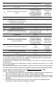
TROUBLESHOOTING LED Status None (LED not on or flashing) One short flash every four seconds Alternates bright and dim (Heartbeat) Control Status Electrical power not present. Stand-by mode, Thermostat is satisfied (no faults). Thermostat calling for heat (no fault). Short flash once every second Weak pilot signal on last call for heat. Short flash once every two seconds Idle remote command off Pressure switch not working-closed position.
Troubleshooting continued- LED Status Control Status Six flashes-two flashes, three second pause (Soft lockout) Pressure switch or blower temperature switch opened during burner operation. System auto resets after 5 minutes. Six flashes-three flashes, three second pause (Soft lockout) Pilot flame extinguished. System resets after 5 minutes. Six flashes-four flashes, three second pause (Soft lockout) Undesired-false pilot flame sensed. System auto resets.
Troubleshooting continued- Control Sequence of Operation Start up Sequence Upon powering up, the control checks for the presence of the vapor sensor, if the resistance is in the expected range the control will begin normal operation after 5 to 8 seconds. Normal Heating Sequence 1. The thermostat senses a need for heat. 2. The control checks the pressure switch condition. 3. If the pressure switch is open, the control sends power to the blower motor. 4.
PARTS LIST DRAWING PARTS LIST PART NAME AND DESCRIPTION 1. Blower Assembly 12. Anode–Nipple 2. Temp. Switch 13. T&P Relief Valve Opening 3. Pressure Switch 14. Pilot Assembly 4. Flue Baffle 15. Main Burner Orifice 5. Gas Control Valve 16. Gas Feedline 6. Drain Valve 17. Flammable Vapors Sensor 7. Fiberglass Insulation (not shown) 18. Sensor Harness 8. Foam Insulation (not shown) 19. Blower Harness 9. Outer Door 20. Inner Door Assembly 10. Steel Burner 21. Adapter 11. Diptube–Nipple 22.
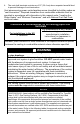
THE FOLLOWING INSTRUCTIONS ARE FOR INSTALLATION OF: GAS WATER HEATERS SUITABLE FOR WATER (POTABLE) HEATING AND SPACE HEATING 1. All piping components connected to this water heater for space heating applications must be suitable for use with potable water. In Massachusetts, space heating piping length must not exceed 50 feet. 2. Toxic chemicals, such as those used for boiler treatment, must not be introduced into potable water used for space heating. 3.
NOTES 46
NOTES 47
NOTES 48