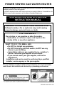
POWER VENTED GAS WATER HEATER A Spanish language version of these instructions is available by contacting the company listed on the rating plate. La version espanola de estas instrucciones se puede obtener al escribirle a la fabrica cuyo nombre aparece en la placa de especificaciones. INSTALLATION AND OPERATING INSTRUCTION MANUAL WARNING: If the information in these instructions is not followed exactly, a fire or explosion may result causing property damage, personal injury, or death.
CONGRATULATIONS! You have purchased one of the finest water heaters on the market today! This installation, operation and instruction manual will explain in detail the installation and maintenance of your new Power Vented Gas Water Heater. We strongly recommend that you contact a plumbing professional for the installation of this water heater. We require that you carefully read this manual, as well as the enclosed warranty, and refer to it when questions arise.
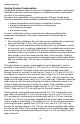
GENERAL INFORMATION This gas-fired water heater is design certified by CSA International under the American National Standard Z21.10.1, CSA 4.1-M, Z21.10.3 and CSA 4.3 most current editions at the time of manufacture. This is a category III water heater. This water heater must be installed in accordance with local codes or, in the absence of local codes, the National Fuel Gas Code, ANSI Z223.1-Latest Edition) and/or in Canada CAN/CGA B149 Installation Codes (Latest Editions).
General Information continued- Make sure that you check the rating plate and combination gas control on the water heater to be certain that the type of gas being supplied corresponds with the marking on the rating plate and combination gas control. A sacrificial anode(s) is used to extend tank life. Removal of any anode, except for inspection and/or replacement, will nullify the warranty.
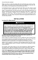
Installation (Locating The Water Heater) continued- Water heater corrosion and component failure can be caused by the heating and breakdown of airborne chemical vapors. Examples of some typical compounds that are potentially corrosive are: spray can propellants, cleaning solvents, refrigerator and air conditioning refrigerants, swimming pool chemicals, calcium and sodium chloride, waxes, and process chemicals.
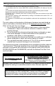
Installation (Locating The Water Heater) continued- The water heater must be located close enough to the outside wall to keep the venting distance within the maximum distance described in the installation instructions. Locate the water heater as close as possible to the vent opening. Read the venting section in this installation instruction manual before locating the water heater.
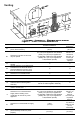
Venting Figure 1 - Vent Terminal Clearances Canadian Installations1 US Installations2 12 inches (30 cm) 4 feet (1.
M= Clearance under a veranda, porch, deck, or balcony 12 inches (30 cm) ‡ *b 1 In accordance with the current CAN/CGA-B149 Installation Codes. In accordance with the current ANSI Z223.1-(Latest edition)/NFPA 54 National Fuel Gas Code. † A vent shall not terminate directly above a sidewalk or paved driveway that is located between two single-family dwellings and serves both dwellings. ‡ Permitted only if a veranda, porch, deck or balcony is fully open on a minimum of two sides beneath the floor.
WARNING Risk of carbon monoxide poisoning or fire due to joint separation or pipe breakage. This water heater must be properly vented and connected to an approved vent system in good condition. DO NOT operate water heater with the absence of an approved vent system. A clean and unobstructed vent system is necessary to allow noxious fumes that could cause injury or loss of life to vent safely and will contribute toward maintaining the water heater’s efficiency.
Venting continued- Venting System Condensation Condensate formation does not occur in all installations of power vented water heaters but should be protected against on installations where condensation can form in the venting system.
Venting continued- TABLE 1 - VENT CONNECTOR LENGTHS FOR 3 inch (7.6 cm) DIAMETER VENT PIPE Maximum Straight # of Minimum Length ft (m) Elbows Terminating Straight (excl. vent 25, 55, & Length ft (m) 48, 65 gal. term) 75 gal. Through the Wall Through the Wall Through the Wall Through the Wall Through the Roof Through the Roof Through the Roof Through the Roof 1 2 3 4 55 (16.8) 50 (15.2) 45 (13.7) 40 (12.2) 45 (13.7) 40 (12.2) 35 (10.7) 30 (9.1) 0 1 2 3 60 (18.3) 55 (16.8) 50 (15.2) 45 (13.7) 50 (15.
Venting continued- CONNECTION TO 3” (7.6 CM) VENT PIPE CONNECTION TO A 3” (7.6 CM) TO 4” (10.2 CM) REDUCER Figure 2 IMPORTANT All of the venting connections must be leak checked with a soap and water solution upon initial start-up of the water heater. Any leaks must be repaired before continuing operation of the water heater. THROUGH THE WALL VENTING (HORIZONTAL VENTING): Cut a 3 1/2 in (8.9 cm) diameter hole in the wall at the point where the vent connector is going to pass through the wall.
Venting continued- THROUGH THE ROOF VENTING (VERTICAL VENTING): Cut the necessary holes through the roof and ceiling and install the vent connector as shown in Figure 4. Make sure that the installation meets the local codes and/or The National Fuel Gas Code ANSI Z223.1 (Latest Edition) or CGA/CAN B149 Installation Code (Latest Edition).
Venting continued- TABLE 3 3 in (7.6 cm) VENT CONNECTOR LENGTHS FROM INSIDE WALL FOR LOW GROUND CLEARANCE INSTALLATIONS Maximum Straight # of Minimum Length ft (m) Elbows Straight Terminating (excl. 25, 55 Length 48, 65 vent and 75 ft (m) gal. term.) gal. 1 40 (12.2) 30 (9.1) 5 (1.5) (2) 90 Elbows with (1) 90 Elbow 2 35 (10.7) 25 (7.6) 5 (1.5) (2) 90 Elbows with (1) 90 Elbow 3 30 (9.1) 20 (6.1) 5 (1.5) (2) 90 Elbows with (1) 90 Elbow 4 25 (7.6) 15 (4.6) 5 (1.
Vent Pipe Preparation and Joining continued- 1) Specific cleaners, solvents, primers and cements are available for PVC, CPVC, and ABS pipe. Be sure these materials match the type of pipe to be installed. The vent pipe manufacturers joining instructions must be followed in all cases. Never use all-purpose cements, commercial glues and adhesives or ABS cement to join PVC or CPVC pipe and fittings. Refer to the table at the beginning of the “VENTING” section for approved primers and cements.
Combustion Air Supply WARNING Liquefied petroleum gases/propane gas are heavier than air and will remain at floor level if there is a leak. Basements, crawl spaces, closets and areas below ground level will serve as pockets for accumulation of leaking gas. Before lighting, smell all around the appliance area for gas. Be sure to smell next to the floor. IF YOU SMELL GAS: • DO NOT try to light any appliance. • DO NOT touch any electric switch; DO NOT use any telephone in your building.
Installation (Combustion Air Supply) continued- All Air From Inside the Building The confined space must be provided with two permanent openings communicating directly with an additional room(s) of sufficient volume so that the combined volume of all spaces meets the criteria for an unconfined space. The total input of all gas utilization equipment installed in the combined space must be considered in making this determination.
Water Connections NOTE: BEFORE PROCEEDING WITH THE INSTALLATION, CLOSE THE MAIN WATER SUPPLY VALVE. After shutting off the main water supply, open a faucet to relieve the water line pressure to prevent any water from leaking out of the pipes while making the water connections to the water heater. After the pressure has been relieved, close the faucet. The COLD water inlet and HOT water outlet are identified on the top of the water heater.
Water Connections continued- WARNING For protection against excessive temperatures and pressure, install temperature and pressure protective equipment required by local codes, but not less than a combination temperature and pressure relief valve certified by a nationally recognized testing laboratory that maintains periodic inspection of production of listed equipment or materials as meeting the requirements of the Standard for Relief Valves and Automatic Gas Shutoff Devices for Hot Water Supply Systems, A
Water Connections continued- WARNING Hydrogen gas can be produced in an operating water heater that has not had water drawn from the tank for a long period of time (generally two weeks or more). HYDROGEN GAS IS EXTREMELY FLAMMABLE. To prevent the possibility of injury under these conditions, we recommend the hot water faucet to be open for several minutes at the kitchen sink before you use any electrical appliance which is connected to the hot water system.
Gas Connections The gas supply lines must meet all requirements of the National Fuel Gas Code (ANSI Z223.1-Latest Edition), or in Canada CAN/CGA B149.1 Natural Gas Installation Code (Latest Edition) or CAN/CGA B149.2 Propane Installation Code (Latest Edition). The minimum permissible gas supply pressure for the purpose of input adjustment is 1 in (0.25 kPa) water column above the operating manifold pressure. See the rating plate and gas valve for the manifold pressure and gas type.
Gas Connections continued- 3. While checking for leaks care must be taken to prevent solution from contacting the electrical connections at the control. If electrical connections at the control become wet, they must be thoroughly dried before attempting to operate the water heater. Electrical Connections All electrical wiring and connections must be in accordance with the National Electric Code ANSI/NFPA No. 70 (Latest Edition), or the Canadian Electrical Code C22.
Wiring Diagram Figure 6 23
GENERAL OPERATION WARNING Water heaters are heat producing appliances. To avoid damage or injury there must be no materials stored against the water heater or vent-air intake system, and proper care must be taken to avoid unnecessary contact (especially by children) with the water heater and vent-air intake system.
Lighting & Shutdown Instructions 25
Thermostat Adjustment The thermostat dial is adjusted to approximately 120°F (49°C) when shipped from the factory. When adjusting the thermostat, it should be remembered that lower temperature settings are more energy efficient. To adjust the thermostat, turn the dial clockwise until the minimum acceptable temperature is set. It is suggested that the starting point setting not exceed the 120°F (49°C) or “HOT” setting on the thermostat.
Burner Flame Check Steel Burner: These models are equipped with self-adjusting air mixture and do not have an adjustable air shutter (see Figure 8). At periodic intervals a visual check of the main burner and pilot flames should be made to determine if they are burning properly. The main burner flame should light smoothly from the pilot. Figure 8 WARNING Do not run out of propane gas. Damage to the water heater may occur. MAINTENANCE WARNING Water heaters are heat producing appliances.
Maintenance continued- The following maintenance should be performed by a qualified service technician at the minimum periodic intervals suggested below. In some installations, the maintenance interval may be more frequent depending on the amount of use and the operating conditions of the water heater. Regular inspection and maintenance of the water heater and vent-air intake system will help to insure safe and reliable operation. 1. Annually check the operation of the thermostat. 2.
Maintenance continued- 7. Monthly drain off a gallon of water to remove silt and sediment. WARNING This water may be HOT. 8. If the combination temperature and pressure relief valve on the appliance discharges periodically, this may be due to thermal expansion in a closed water supply system. Contact the water supplier or local plumbing inspector on how to correct this situation. Do not plug the combination temperature and pressure relief valve outlet. 9.
Maintenance continued- CAUTION FOR YOUR SAFETY, DO NOT ATTEMPT REPAIR OF COMBINATION GAS CONTROL, BURNERS OR GAS PIPING. REFER REPAIRS TO A QUALIFIED SERVICE TECHNICIAN. Contact your supplier or plumbing professional for replacement parts or contact the company at the address given on the rating plate of the water heater. Provide the part name, model and serial numbers of the water heater when ordering parts.
Troubleshooting LED Status Control Status None (LED not on or flashing) Electrical power not present. Stand-by mode, Thermostat is satisfied (no faults). Thermostat calling for heat (no fault). One short flash every four seconds Alternates bright and dim (Heartbeat) Probable Cause Control power switch in “OFF” position. Supply voltage interrupted. Temperature demand is satisfied (no call for heat). Tank temperature below set point of thermostat. 1. Unstable pilot. 2. Pilot tube block or restricted. 3.
Troubleshooting continued- LED Status Control Status Probable Cause Six flashes-three flashes, three second pause (Soft lockout) Pilot flame extinguished. System resets after 5 minutes. 1. Unstable pilot. 2. Pilot tube blocked or restricted. 3. Oxidation build up on pilot electrode. 4. Wire damage to pilot assembly or bad connection at gas valve. 5. Insufficient combustion air. Six flashes-four flashes, three second pause (Soft lockout) Undesired-false pilot flame sensed. System auto resets.
Troubleshooting continued- Control Sequence of Operation Start up Sequence Upon powering up, the control checks for the presence of the resistive plug, if the resistance is in the expected range the control will begin normal operation after 5 to 8 seconds. Normal Heating Sequence 1. The thermostat senses a need for heat. 2. The control checks the pressure switch condition. 3. If the pressure switch is open, the control sends power to the blower motor. 4.
PARTS LIST DRAWING (ACTUAL WATER HEATER VISUAL REPRESENTATION MAY VARY) PART NAME AND DESCRIPTION 1. Blower Assembly 2. Pressure Switch (not shown) 3. Blower Temp. Switch (not shown) 4. Flue Baffle or Flue Core 5. Flue Baffle Reducer 6. Anode-Nipple 7. Diptube-Nipple 8. Gas Valve 9. Resistive Device 10. Drain Valve 34 11. Inner Door (Left) 12. Inner Door (Right) 13. Screw (Inner Door) 14. Outer Door 15. Screw (Outer Door) 16. T & P Valve 17. Gas Feedline 18. Gas Pilot 19. Burner 20.
THE FOLLOWING INSTRUCTIONS ARE FOR INSTALLATION OF: GAS WATER HEATERS SUITABLE FOR WATER (POTABLE) HEATING AND SPACE HEATING 1. All piping components connected to this water heater for space heating applications must be suitable for use with potable water. In Massachusetts, space heating piping length must NOT exceed 50 ft. 2. Toxic chemicals, such as those used for boiler treatment, must NOT be introduced into potable water used for space heating. 3.
NOTES 36