
Installation / Operation Instruction Manual


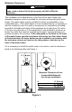
Table Of Contents
- TABLE OF CONTENTS
- INSTALLATION
- Figure 1
- Probable Cause
- Control Status
- LED Status
- Millivolt power is not present. Light pilot.
- None (LED not on or flashing)
- Gas valve is powered and waiting for the set point knob to be turned to a water temperature setting. If the set point knob is at desired setting the thermostat is satisfied.
- If set point knob is in “PILOT” position, then pilot flame is detected. (no faults).
- One flash and three second pause.
- LED strobe (two quick flashes) and three second pause.
- Thermostat calling for heat (no faults).
- Water heater operating normally
- Set point know was recently turn to “OFF” position. Wait until LED goes out before attempting to relight.
- Set point knob has been recently turned to the “OFF” position.
- LED on continuously.
- Weak pilot flame detected. System will reset when pilot flame is sufficient.
- Two flashes and three second pause.
- Insufficient water heating. System will reset.
- Three flashes and three second pause
- Excessive tank temperature. System must be reset.
- Four flashes and three second pause
- Probable Cause
- Control Status
- LED Status
- Five flashes and three second pause.
- Temperature sensor fault.
- Water leak detected by accessory module (some models).
- Six flashes and three second pause.
- Gas valve electronic fault detected.
- Seven flashes and three second pause.
- Eight flashes and three second pause.
- False pilot flame present.

9
Combustion Air Supply
Provide adequate air for combustion and ventilation. An insufficient
supply of air will cause recirculation of combustion products resulting in
air contamination that may be hazardous to life. Such a condition often
will result in a yellow, luminous burner flame, causing carboning or
sooting of the combustion chamber, burners and flue tubes with possible
damage to the water heater. When an exhaust fan is installed in the
same room with a water heater, sufficient openings for air must be
provided in the walls. Undersized openings will cause air to be drawn
into the room through the chimney, causing recirculation of combustion
products.
Confined Spaces
Confined spaces are spaces defined as having less than 50 ft.
3
/1000 BTU
(1.41m
3
/.29kw) per hour.
Unconfined Spaces
In unconfined spaces in buildings, infiltration may be adequate to provide air
for combustion, ventilation and dilution of flue gases. However, in buildings of
tight construction (for example, weather stripping, heavily insulated, caulked,
vapor barrier, etc.), additional air may need to be provided using the methods
described above under CONFINED SPACES: All Air from Outdoors or
SPECIALLY ENGINEERED INSTALLATIONS.
WARNING
Liquefied petroleum gases/propane gases are heavier than air and will
remain at floor level if there is a leak. Basements, crawl spaces, closets
and areas below ground level will serve as pockets for accumulation of
leaking gas. Before lighting, smell all around the appliance area for
gas. Be sure to smell next to the floor.
IF YOU SMELL GAS:
• Do not try to light any appliance.
• Do not touch any electric switch; do not use any telephone in your
building.
• Immediately call your gas supplier from a neighbor’s telephone.
Follow the gas supplier’s instructions.
• If you cannot reach your gas supplier, call the fire department.
DO NOT OPERATE APPLIANCE UNTIL LEAKAGE IS CORRECTED!
IMPORTANT
The flow of combustion and ventilating air must not be obstructed.