
Installation / Operation Instruction Manual


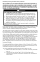
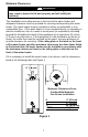
Table Of Contents
- TABLE OF CONTENTS
- INSTALLATION
- Figure 1
- Probable Cause
- Control Status
- LED Status
- Millivolt power is not present. Light pilot.
- None (LED not on or flashing)
- Gas valve is powered and waiting for the set point knob to be turned to a water temperature setting. If the set point knob is at desired setting the thermostat is satisfied.
- If set point knob is in “PILOT” position, then pilot flame is detected. (no faults).
- One flash and three second pause.
- LED strobe (two quick flashes) and three second pause.
- Thermostat calling for heat (no faults).
- Water heater operating normally
- Set point know was recently turn to “OFF” position. Wait until LED goes out before attempting to relight.
- Set point knob has been recently turned to the “OFF” position.
- LED on continuously.
- Weak pilot flame detected. System will reset when pilot flame is sufficient.
- Two flashes and three second pause.
- Insufficient water heating. System will reset.
- Three flashes and three second pause
- Excessive tank temperature. System must be reset.
- Four flashes and three second pause
- Probable Cause
- Control Status
- LED Status
- Five flashes and three second pause.
- Temperature sensor fault.
- Water leak detected by accessory module (some models).
- Six flashes and three second pause.
- Gas valve electronic fault detected.
- Seven flashes and three second pause.
- Eight flashes and three second pause.
- False pilot flame present.

7
Minimum Clearances
This installation must allow access to the front of the water heater and
adequate clearance must be provided for servicing and operating this water
heater. The water heater may be installed on either a combustible or non-
combustible floor. If the water heater is to be installed directly on carpeting, it
must be installed on top of a metal or wood panel (or equivalent) extending
beyond the full width and depth of the appliance by at least three (3) inches
(7.6 cm) in any direction or, if the appliance is to be installed in an alcove or
closet, the entire floor must be covered by the panel, increase distances to
provide clearance for servicing. If the rating plate or the label on the front
of the water heater specifies minimum clearances less than those listed
in the below table, the water heater may be installed in accordance with
the minimum clearances listed on the rating plate or the label on the
front of the water heater.
If it is necessary to install this water heater in an alcove, use the clearances
listed in the following table and Figure 1.
Minimum Clearances From
Combustible Materials
For Alcove Installation
A 6” (0.0cm)
B 6” (0.0cm)
C 16” (40.6 cm)
VENT 6” (15.2cm)
Figure 1
WARNING
Failure to adhere to these installation and operating instructions
may create a hazard to life and property and will nullify the
warranty.