GAS-FIRED WATER HEATER A Spanish language version of these instructions is available by contacting the company listed on the rating plate. La version española de estas instrucciones se puede obtener al escribirle a la fábrica cuyo nombre aparece en la placa de especificaciones. INSTALLATION & OPERATING INSTRUCTION MANUAL WARNING: If the information in these instructions is not followed exactly, a fire or explosion may result causing property damage, personal injury or death.
CONGRATULATIONS! You have just purchased one of the finest water heaters on the market today! This installation, operation and instruction manual will explain in detail the installation and maintenance of your new Gas Water Heater. We strongly recommend that you contact a plumbing professional for the installation of this water heater. We require that you carefully read this manual, as well as the enclosed warranty, and refer to it when questions arise.
GENERAL INFORMATION This gas-fired water heater is design certified by CSA International under the applicable American National Standard, Z21.10.1 or Z21.10.3 (as indicated on the rating plate), or CSA 4.1 (as indicated on the rating plate), available from CSA International, 8501 East Pleasant Valley Road, Cleveland, OH U.S.A. 44131-5575. This water heater must be installed in accordance with local codes.
General Information continued- This water heater has been manufactured for operation at altitudes from sea level to 2000 feet (610m). For use of this appliance at an elevation greater than 2000 feet (610m), contact the dealer or manufacturer listed on the rating plate for information on any necessary modification. Uncorrected operation of this appliance may create a hazard to life and property.
Installation (Locating the Water Heater) continued- Water heaters in residential garages must be installed so that all burner(s) and burner ignition device(s) are located not less than 18 inches (45.7 cm) above the floor and be located, or protected, to avoid physical damage. For other installations refer to local codes. In the absence of local codes, the water heater must be installed in compliance with the National Fuel Gas Code, (ANSI Z223.1- Latest Edition), or in Canada CAN/CGA B149.
Installation (Locating the Water Heater) continued- NOTE: DAMAGE TO THE WATER HEATER CAUSED BY EXPOSURE TO CORROSIVE VAPORS IS NOT COVERED BY THE WARRANTY. DO NOT OPERATE THE WATER HEATER IF EXPOSURE HAS OR WILL OCCUR. DO NOT STORE ANY POTENTIALLY CORROSIVE COMPOUNDS IN THE VICINITY OF THE WATER HEATER.
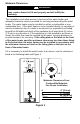
Minimum Clearances WARNING Failure to adhere to these installation and operating instructions may create a hazard to life and property and will nullify the warranty. This installation must allow access to the front of the water heater and adequate clearance must be provided for servicing and operating this water heater. The water heater may be installed on either a combustible or noncombustible floor.
Venting WARNING The venting system must be installed properly following all local codes or in the absence of local codes, the latest edition of the National Fuel Gas Code (ANSI Z223.1- latest edition), or in Canada, The Natural Gas and Propane Installation Code (B149.1-00 latest edition). Failure to properly install the venting system could result in property damage, personal injury, or death.
Combustion Air Supply WARNING Liquefied petroleum gases/propane gases are heavier than air and will remain at floor level if there is a leak. Basements, crawl spaces, closets and areas below ground level will serve as pockets for accumulation of leaking gas. Before lighting, smell all around the appliance area for gas. Be sure to smell next to the floor. IF YOU SMELL GAS: • Do not try to light any appliance. • Do not touch any electric switch; do not use any telephone in your building.
Installation (Combustion Air Supply) continued- All Air from Inside the Building: The confined space must be provided with two permanent openings communicating directly with an additional room(s) of sufficient volume so that the combined volume of all spaces meets the criteria for an unconfined space. The total input of all gas utilization equipment installed in the combined space must be considered in making this determination. Each opening must have a minimum free area of 1 square inch per 1000 BTU (6.
Water Connections Note: BEFORE PROCEEDING WITH THE INSTALLATION, CLOSE THE MAIN WATER SUPPLY VALVE. After shutting off the main water supply, open a faucet to relieve the water line pressure to prevent any water from leaking out of the pipes while making the water connections to the water heater. After the pressure has been relieved, close the faucet. The COLD-water inlet and HOT water outlet are identified on the top of the water heater.
Installation (Water Connections) continued- WARNING For protection against excessive temperatures and pressure, install temperature and pressure protective equipment required by local codes, but not less than a combination temperature and pressure relief valve certified by a nationally recognized testing laboratory that maintains periodic inspection of production of listed equipment or materials as meeting the requirements of the Standard for Relief Valves and Automatic Gas Shutoff Devices for Hot Water Su
Installation (Water Connections) continued- WARNING Hydrogen gas can be produced in an operating water heater that has not had water drawn from the tank for a long period of time (generally two weeks or more). Hydrogen gas is extremely flammable. To prevent the possibility of injury under these conditions, we recommend the hot water faucet to be open for several minutes at the kitchen sink before you use any electrical appliance, which is connected to the hot water system.
Gas Connections The gas supply lines must meet all requirements of the National Fuel Gas Code (ANSI Z223.1Latest Edition), or in Canada CAN/CGA B149.1 Natural Gas Installation Code (Latest Edition) or CAN/CGA B149.2 Propane Installation Code (Latest Edition). The minimum permissible gas supply pressure for the purpose of input adjustment is one (1.0) inch (0.25 kPa) water column above the operating manifold pressure. See the rating plate and gas valve for the manifold pressure and gas type.
GENERAL OPERATION WARNING Water heaters are heat producing appliances. To avoid damage or injury there must be no materials stored against the water heater or vent-air intake system, and proper care must be taken to avoid unnecessary contact (especially by children) with the water heater and vent-air intake system.
Lighting & Shutdown Instructions - White Rodgers Mechanical Gas Control.
Lighting & Shutdown Instructions - White Rodgers Electronic Gas Control.
Lighting & Shutdown Instructions - Honeywell Gas Controls.
THERMOSTAT ADJUSTMENT - White Rodgers Mechanical Gas Control.
THERMOSTAT ADJUSTMENT – Honeywell Gas Control V1. THERMOSTAT ADJUSTMENT – Honeywell Gas Control V2.
DANGER Hotter water increases the risk of scald injury. Scalding may occur within five (5) seconds at a temperature setting of 140°F (60°C). To protect against hot water injury, install an ASSE approved mixing valve in the water system. This valve will reduce point of discharge temperature by mixing cold and hot water in branch water lines. A licensed plumbing professional or local plumbing authority should be consulted.
MAINTENANCE WARNING Water heaters are heat producing appliances. To avoid damage or injury there must be no materials stored against the water heater or vent-air intake system, and proper care must be taken to avoid unnecessary contact (especially by children) with the water heater and vent-air intake system.
Maintenance Continued6. At least once a year, check the combination temperature and pressure relief valve to ensure that the valve has not become encrusted with lime. Lift the lever at the lever at the top of the valve several times until the valve seats properly without leaking and operates freely. 7. Monthly drain off a gallon of water to remove silt and sediment. WARNING THIS WATER MAY BE HOT. 8.
TROUBLESHOOTING CHART – HONEYWELL V1. LED Status Control Status None (LED not on or flashing) Millivolt power is not present. Light pilot. One flash and three second pause. If set point knob is in “PILOT” position, then pilot flame is detected. (no faults). LED strobe (two quick flashes) and three second pause. Thermostat calling for heat (no faults). LED on continuously. Set point knob has been recently turned to the “OFF” position. Two flashes and three second pause.
TROUBLESHOOTING CHART – HONEYWELL V1 continued. LED Status Control Status Five flashes and three second pause. Temperature sensor fault. Six flashes and three second pause. Water leak detected by accessory module (some models). Seven flashes and three second pause. Gas valve electronic fault detected. Eight flashes and three second pause. False pilot flame present. 25 Probable Cause 1. Damage to the temperature wire. 2. Temperature sensor resistance out of range. 3. Replace temperature sensor. 4.
TROUBLESHOOTING CHART – HONEYWELL V2. LED Status One flash every four seconds (LED green) Control Status Not an error. Indicates control is in OFF mode. Pilot is off. Not an error. Indicates pilot is lit and main burner is off. One flash every second (LED green) Not an error. Indicates main valve is open and main burner is lit. None. Control will automatically shut main burner off when water temperature reaches the setpoint temperature.
TROUBLESHOOTING CHART – WHITE RODGERS ELECTRONIC. LED Status None (LED not on or flashing) Control Status Indicates control is off. Main and pilot burner are off. Probable Cause Gas valve is functioning normally. Gas valve is not powered. Light pilot. Not an error. Indicates main valve is open and main burner is lit. Not an error. Indicates that the control is in shutdown mode. Gas valve is powered and waiting for the set point knob to be turned to a water temperature setting.
Troubleshooting continuedManufactured under one or more of the following U.S. Patents: 5,277,171; 5,341,770; 5,372,185; 5,485,879; 5,574,822; 5,596,952; 5,660,165; 5,682,666; 5,761,379; 5,943,984; 5,954,492; 5,988,117; 6,056,542; 6,142,216; 6,442,178; 6,684,821; 6,935,280; 7,063,132; 7,063,133; 7,007,748; 7,270,087; 7,334,419; 7,337,517; 7,409,925; 7,458,341; 7,559,293; 7,621,238; 7,634,976; 7,650,859; 7,665,210; 7,665,211; 7,699,026; 7,866,168; 7,900,589; 7,971,560; 7,992,526 8,082,888; 8,146,772; Other U.
Troubleshooting continued- Figure 12 29
PARTS LIST AND DRAWING 1 2 3 4 5 7 6 8 2 9 2 10 8 11 12 13 14 15 16 17 18 19 20 22 21 23 PART NAME AND DESCRIPTION 1. Draft Diverter 2. Hole Closure 3. Flue Reducer 4. Magnesium Anode 5. Nipple 6. Flue Baffle Assembly 7. Dip Tube-Cold Water Inlet 8. Escutcheon 9. Temperature and Pressure Relief Valve 10. Combination Gas Control and Thermostat 11. Drain Valve 12. Inner Door (Left Side) 13. Hex Screw 10-12 x 3/4 14. Radiation Shield 15. Inner Door (Right Side) 16. Hex Screw 8-15 x 3/4 17.
THE FOLLOWING INSTRUCTIONS ARE FOR INSTALLATION OF: GAS WATER HEATERS SUITABLE FOR WATER (POTABLE) HEATING AND SPACE HEATING 1. All piping components connected to this water heater for space heating applications must be suitable for use with potable water. In Massachusetts, space heating piping length must not exceed 50 feet. 2. Toxic chemicals, such as those used for boiler treatment, must not be introduced into potable water used for space heating. 3.
NOTES 32