
Spec Sheet

©2022, Bradford White Corporation, USA. All rights reserved.
Sales: 800-523-2931
n
Fax 215-641-1612
24/7 Technical Support: 800-334-3393
n
Email techserv
@
bradfordwhite.com
Products made by Bradford White are manufactured in the United States using the finest raw materials and components from around the world.
NATURAL GAS AND LIQUID PROPANE GAS
Model
Number
Capacity
Combi1
®
Models
F
Floor
to
Exchanger
Inlet
in.
C
Vent
Size
in.
Approx.
Shipping
Weight
lbs.
E
Floor
to
Gas
Conn.
in.
A
Floor to
Flue
Conn.
in.
D
Floor to
T&P
Conn.
in.
J
Floor
to
Water
Conn.
in.
B
Jacket
Dia.
in.
Gal.
U.S.
Input
Nat.
BTU/Hr.
Input
LP
BTU/Hr.
GPH
Nat.
U.S.
Recovery
90°F Rise*
Model
Number
Capacity
Liters
F
Floor
to
Exchanger
Inlet
mm.
C
Vent
Size
mm.
Approx.
Shipping
Weight
kg.
E
Floor
to
Gas
Conn.
mm.
A
Floor to
Flue
Conn.
mm.
D
Floor to
T&P
Conn.
mm.
J
Floor
to
Water
Conn.
mm.
B
Jacket
Dia.
mm.
Input
Nat.
kW
Input
LP
kW
Hour
Nat.
Liters/
Hour
LP
Liters/
Recovery
50°C Rise*
Meet or exceed ASHRAE 90.1b (current standard) C.E.C. Listed
80% Recovery Efficiency
45
72
Gal.
Imp.
38
61
65,000
76,000
61,000
76,000
22
26
236
292
4
4
70
81
GPH
LP
U.S.
66
81
GPH
Nat.
Imp.
59
70
GPH
LP
Imp.
55
70
C-SW2-504T10FBN
C-SW2-75T10BN
C-SW2-504T10FBN
C-SW2-75T10BN
170
272
250
317
1505
1581
559
660
1270
1314
330
352
800
752
G
Floor
to
Exchanger
Outlet
in.
G
Floor
to
Exchanger
Outlet
mm.
1270
1314
H
Floor
to
Top of
Heater
in.
H
Floor
to
Top of
Heater
mm.
1432
1499
102
102
107
128
1534
1600
K
Depth
in.
K
Depth
mm.
622
772
17.9
22.3
19.1
22.3
265
317
59
1
/4
62
1
/4
50
51
3
/4
13
13
7
/8
31
1
/3
29
5
/8
50
51
3
/4
56
3
/8
59
60
3
/8
63
24
1
/2
30
3
/8
Residential Atmospheric Vent Combi1
®
Gas Water Heater System
General
Meets NAECA Requirements.
All gas water heaters are certified at 300 PSI test pressure (2068 kPa) and 150 PSI working pressure (1034 kPa). All potable water connections are 3/4" NPT
(19mm) on 11" (279mm) centers. All heat exchanger connections are 1" NPT (25mm). All gas connections 1⁄2" (13mm).
All models design certified by CSA International (formerly AGA/CGA), ANSI Z21.10.1 and peak performance rated.
Dimensions and specifications subject to change without notice in accordance with our policy of continuous product improvement.
Suitable for Water (Potable) Heating and Space Heating. Toxic chemicals, such as those used for boiler treatment, shall NEVER be introduced into the
potable water side. The potable side of this unit may NEVER be connected to any existing heating system or component(s) previously used with a non-potable
water heating appliance. The heat exchanger side of the unit may be used in space heating applications.
Propane model features a Titanium Stainless Steel propane burner. For propane (LP) models change suffix “BN” to “SX”.
* Based on manufacturers rated recovery efficiency.
Heat Exchanger Values*
Supply Temperature
Return Temperature
Differential
Flow Rate (C-SW2-504T10FBN)
Flow Rate (C-SW2-75T10BN)
Net Output (C-SW2-504T10FBN)
Net Output (C-SW2-75T10BN)
140°F
120°F
20°F
4.1 GPM
4.1 GPM
35,500 BTU/Hr.
35,500 BTU/Hr.
60°C
49°C
11°C
15.5 LPM
15.5 LPM
10.4 kW
10.4 kW
49°C
38°C
11°C
17.4 LPM
21.2 LPM
11.6 kW
14.0 kW
38°C
27°C
11°C
17.4 LPM
21.2 LPM
11.6 kW
14.0 kW
120°F
100°F
20°F
4.6 GPM
5.6 GPM
39,500 BTU/Hr.
47,500 BTU/Hr.
100°F
80°F
20°F
4.6 GPM
5.6 GPM
39,500 BTU/Hr.
47,500 BTU/Hr.
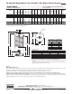
K
C
A
J
H
E
F
D & G
B
PLUG TYPE
ANODE
K
C
A
J
H
E
F
D & G
B
PLUG TYPE
ANODE
* These values were obtained using 180°F (82°C) stored tan temperature.
Net Output is the space heating capacity based on normal piping and pickup allowance
of 15%.
Actual values may vary based on circulator flow rate, number of zones, water and space
heating demands. Numbers subject to change.
Heat Exchanger
Head Loss
GPM
2
5
8
10
12
Ft. of
Hd. Loss
0.03
0.20
0.51
0.80
1.15
Heat Exchanger
Head Loss
LPM
7.6
18.9
30.2
37.9
45.4
m of
Hd. Loss
0.0091
0.0609
0.1554
0.2438
0.3505
Printed in U.S.A.548-G-0122