
Installation / Operation Instruction Manual

238-46299-00D REV 09/13
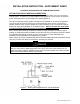
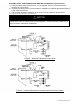
SYSTEM LAYOUT FOR COMBI2 WATER HEATING SYSTEM (See Figures 2 and 3)
1) Install a properly sized expansion tank. An air separator and vent is recommended to
eliminate air in the system.
2) A pressure reducing valve is recommended for installation to maintain appropriate pressure
in the closed loop system.
3) The circulator should be installed to “pump away” from the expansion tank as shown.
4) Purge all air from the filled, closed system.
NOTICE
The Combi water heater can experience condensation conditions longer than other water
heaters as the hydronic system comes up to temperature. These condensing conditions can
extend for days in radiant floor installations.
Figure 2 – Hydronic Piping with Zone Valves
Figure 3 – Hydronic Piping with Circulators and Flow Control Valves