
Installation / Operation Instruction Manual
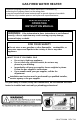
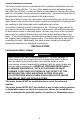
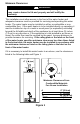
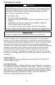
Table Of Contents
- TABLE OF CONTENTS
- INSTALLATION
- Figure 1
- Probable Cause
- Control Status
- LED Status
- Millivolt power is not present. Light pilot.
- None (LED not on or flashing)
- Gas valve is powered and waiting for the set point knob to be turned to a water temperature setting. If the set point knob is at desired setting the thermostat is satisfied.
- If set point knob is in “PILOT” position, then pilot flame is detected. (no faults).
- One flash and three second pause.
- LED strobe (two quick flashes) and three second pause.
- Thermostat calling for heat (no faults).
- Water heater operating normally
- Set point know was recently turn to “OFF” position. Wait until LED goes out before attempting to relight.
- Set point knob has been recently turned to the “OFF” position.
- LED on continuously.
- Weak pilot flame detected. System will reset when pilot flame is sufficient.
- Two flashes and three second pause.
- Insufficient water heating. System will reset.
- Three flashes and three second pause
- Excessive tank temperature. System must be reset.
- Four flashes and three second pause
- Probable Cause
- Control Status
- LED Status
- Five flashes and three second pause.
- Temperature sensor fault.
- Water leak detected by accessory module (some models).
- Six flashes and three second pause.
- Gas valve electronic fault detected.
- Seven flashes and three second pause.
- Eight flashes and three second pause.
- False pilot flame present.

6
Installation (Locating the Water Heater) continued-
NOTE: DAMAGE TO THE WATER HEATER CAUSED BY EXPOSURE TO
CORROSIVE VAPORS IS NOT COVERED BY THE WARRANTY. DO NOT
OPERATE THE WATER HEATER IF EXPOSURE HAS OR WILL OCCUR.
DO NOT STORE ANY POTENTIALLY CORROSIVE COMPOUNDS IN THE
VICINITY OF THE WATER HEATER.
Proper venting practices must be considered when selecting a location for this
water heater. For exact venting specifications, please consult the Venting
section, of these Installation and Operating Instructions.
This water heater must be located in an area where leakage of the tank, water
line connections, or the combination temperature and pressure relief valve will
not result in damage to the area adjacent to the water heater or to lower floors
of the structure. When such locations cannot be avoided, a suitable drain pan
must be installed under the water heater. The drain pan must have a
minimum length and width of at least 4 in. (10.2 cm) greater than the diameter
of the water heater and must not restrict proper combustion air flow to the
water heater. The drain pan, as described above, can be purchased from
your plumbing professional. The drain pan must be piped to an adequate
drain. The piping must be at least 3/4 inch (1.9 cm) in diameter and pitched
for proper drainage.
It is recommended that a minimum clearance of four (4) inches (10.2 cm) be
provided on the side of the water heater for servicing and maintenance of the
combination temperature and pressure relief valve.
To comply with NSF requirements this water heater is to be:
a) Sealed to the floor with sealant, in a smooth and easily cleanable
way, or
b) Installed with an optional leg kit that includes legs and/or
extensions that provide a minimum clearance of 6” beneath the
water heater.
WARNING
DO NOT ATTEMPT TO LIGHT ANY GAS APPLIANCE IF YOU ARE
NOT CERTAIN OF THE FOLLOWING:
• Liquefied petroleum gases/propane gas and natural gas have an
odorant added by the gas supplier that aids in detection of the gas.
• Most people recognize this odor as a “sulfur” or “rotten egg” smell.
• Other conditions, such as “odorant fade” can cause the odorant to
diminish in intensity, or “fade”, and not be as readily detectable.
• If you have a diminished sense of smell or are in any way unsure of
the presence of gas, immediately contact your gas supplier from a
neighbor’s telephone.
Gas detectors are available. Contact your gas supplier or plumbing
professional for more information.