
Installation / Operation Instruction Manual
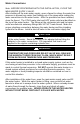
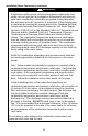
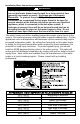
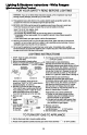
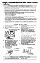
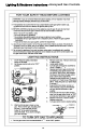
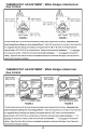
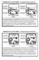
Table Of Contents
- TABLE OF CONTENTS
- INSTALLATION
- Figure 1
- Probable Cause
- Control Status
- LED Status
- Millivolt power is not present. Light pilot.
- None (LED not on or flashing)
- Gas valve is powered and waiting for the set point knob to be turned to a water temperature setting. If the set point knob is at desired setting the thermostat is satisfied.
- If set point knob is in “PILOT” position, then pilot flame is detected. (no faults).
- One flash and three second pause.
- LED strobe (two quick flashes) and three second pause.
- Thermostat calling for heat (no faults).
- Water heater operating normally
- Set point know was recently turn to “OFF” position. Wait until LED goes out before attempting to relight.
- Set point knob has been recently turned to the “OFF” position.
- LED on continuously.
- Weak pilot flame detected. System will reset when pilot flame is sufficient.
- Two flashes and three second pause.
- Insufficient water heating. System will reset.
- Three flashes and three second pause
- Excessive tank temperature. System must be reset.
- Four flashes and three second pause
- Probable Cause
- Control Status
- LED Status
- Five flashes and three second pause.
- Temperature sensor fault.
- Water leak detected by accessory module (some models).
- Six flashes and three second pause.
- Gas valve electronic fault detected.
- Seven flashes and three second pause.
- Eight flashes and three second pause.
- False pilot flame present.

11
Water Connections
Note: BEFORE PROCEEDING WITH THE INSTALLATION, CLOSE THE
MAIN WATER SUPPLY VALVE.
After shutting off the main water supply, open a faucet to relieve the water line
pressure to prevent any water from leaking out of the pipes while making the
water connections to the water heater. After the pressure has been relieved,
close the faucet. The COLD-water inlet and HOT water outlet are identified on
the top of the water heater. The fittings at the cold-water inlet and hot water
outlet are dielectric waterway fittings with 3/4” NPT male thread. Make the
proper plumbing connections between the water heater and the plumbing
system to the house. Install a shut-off valve in the cold-water supply line.
If this water heater is installed in a closed water supply system, such as the
one having a back-flow preventer in the cold-water supply, provisions must be
made to control thermal expansion. DO NOT operate this water heater in a
closed system without provisions for controlling thermal expansion. Your
water supplier or local plumbing inspector should be contacted on how to
control this situation
After installation of the water lines, open the main water supply valve and fill
the water heater. While the water heater is filling, open several hot water
faucets to allow air to escape from the water system. When a steady stream
of water flows through the faucets, close them and check all water
connections for possible leaks. NEVER OPERATE THE WATER HEATER
WITHOUT FIRST BEING CERTAIN IT IS FILLED WITH WATER.
CAUTION
If sweat fittings are to be use, DO NOT apply heat to the nipples on top
of the water heater. Sweat the tubing to the adapter before fitting the
adapter to the water connections. It is imperative that heat is not
applied to the nipples containing a plastic liner.
WARNING
FAILURE TO INSTALL AND MAINTAIN A NEW, LISTED 3/4” X 3/4”
TEMPERATURE AND PRESSURE RELIEF VALVE WILL RELEASE
THE MANUFACTURER FROM ANY CLAIM, WHICH MIGHT RESULT
FROM EXCESSIVE TEMPERATURE AND PRESSURES.