
Installation / Operation Instruction Manual
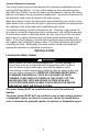
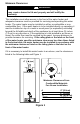
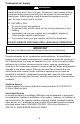
Table Of Contents
- TABLE OF CONTENTS
- INSTALLATION
- Figure 1
- Probable Cause
- Control Status
- LED Status
- Millivolt power is not present. Light pilot.
- None (LED not on or flashing)
- Gas valve is powered and waiting for the set point knob to be turned to a water temperature setting. If the set point knob is at desired setting the thermostat is satisfied.
- If set point knob is in “PILOT” position, then pilot flame is detected. (no faults).
- One flash and three second pause.
- LED strobe (two quick flashes) and three second pause.
- Thermostat calling for heat (no faults).
- Water heater operating normally
- Set point know was recently turn to “OFF” position. Wait until LED goes out before attempting to relight.
- Set point knob has been recently turned to the “OFF” position.
- LED on continuously.
- Weak pilot flame detected. System will reset when pilot flame is sufficient.
- Two flashes and three second pause.
- Insufficient water heating. System will reset.
- Three flashes and three second pause
- Excessive tank temperature. System must be reset.
- Four flashes and three second pause
- Probable Cause
- Control Status
- LED Status
- Five flashes and three second pause.
- Temperature sensor fault.
- Water leak detected by accessory module (some models).
- Six flashes and three second pause.
- Gas valve electronic fault detected.
- Seven flashes and three second pause.
- Eight flashes and three second pause.
- False pilot flame present.
10
Installation (Combustion Air Supply) continued-
All Air from Inside the Building: The confined space must be provided with
two permanent openings communicating directly with an additional room(s) of
sufficient volume so that the combined volume of all spaces meets the criteria
for an unconfined space. The total input of all gas utilization equipment
installed in the combined space must be considered in making this
determination. Each opening must have a minimum free area of 1 square
inch per 1000 BTU (6.45cm
2
/.29kw) per hour of the total input rating of all gas
utilization equipment in the confined space, but not less than 100 square
inches (645cm
2
). One opening must be within 12 inches (31cm) of the top
and one within 12 inches (31cm) of the bottom of the enclosure.
All Air from Outdoors: The confined space must be provided with two
permanent openings, one commencing within 12 inches (31cm) of the top and
one commencing within 12 inches (31cm) from the bottom of the enclosure.
The openings must communicate directly, or by ducts, with the outdoors or
spaces (crawl or attic) that freely communicate with the outdoors.
1. When directly communicating with the outdoors, each opening must have
a minimum free area of 1 square inch per 4000 BTU (6.45cm
2
/1.2kw) per
hour of total input rating of all equipment in the enclosure.
2. When communicating with the outdoors through vertical ducts, each
opening must have a minimum free area of 1 square inch per 4000 BTU
(6.45cm
2
/1.2kw) per hour of total input rating of all equipment in the
enclosure.
3. When communicating with the outdoors through horizontal ducts, each
opening must have a minimum free area of 1 square inch per 2000 BTU
(6.45cm
2
/.6kw) per hour of total input rating of all equipment in the
enclosure.
4. When ducts are used, they must be of the same cross-sectional area as
the free area of the openings to which they connect. The minimum
dimension of rectangular air ducts must be not less than 3 inches (7.5cm)
Specially Engineered Installations
The requirements noted under CONFINED SPACES above shall not
necessarily govern when special engineering, approved by the authority
having jurisdiction, provides an adequate supply of air for combustion,
ventilation, and dilution of flue gases.