
Installation / Operation Instruction Manual
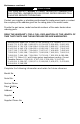
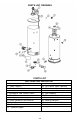
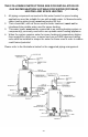

Table Of Contents

46
PARTS LIST DRAWING
PARTS LIST
PART NAME AND DESCRIPTION
1. Blow er Assembly
12. Anode- -- Nipple
2. Temp. Sw itch
13. T&P Relief Valve Opening
3. Pressure Sw itch
14. Pilot Assembly
4. Flue Baffle
15. Main Burner Orifice
5. Honeywell Gas Control Valve
16. Gas Feedline
6. Drain Valve
17. Flammable Vapors Sensor
7. Fiberglass Insulation (not shown)
18. Sensor Harness
8. Foam Insulation (not shown)
19. Blower Harness
9. Outer Door
20. Inner Door Assembly
10. Steel Burner
21. Adapter
11. Diptube- -- Nipple
22. Vapor sensor bracket