
Installation / Operation Instruction Manual
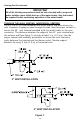
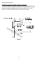
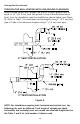
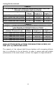
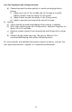
Table Of Contents

24
Venting (Part II) continued-
TABLE 7
2” (5.1 cm) VENT PIPE LENGTHS FROM INSIDE WALL FOR LOW
GROUND CLEARANCE INSTALLATIONS
Terminating
# of
Elbows
Max straight
Length ft (m)
Min straight
Length ft (m)
(2) 90° Elbows with Vent Terminal
1
30 (9.1)
2 (.6)
(2) 90° Elbows with Vent Terminal
2
25 (7.6)
2 (.6)
(2) 90° Elbows with Vent Terminal
3
20 (6.1)
2 (.6)
(2) 90° Elbows with Vent Terminal
4
15 (4.6)
2 (.6)
TABLE 8
3” (7.6 cm) VENT CONNECTOR LENGTHS FROM INSIDE WALL FOR
LOW GROUND CLEARANCE INSTALLATIONS
Terminating (Reduce 3” to 2”)
(Reduce 7.6 cm to 5.1 cm)
#of
Elbows
Maximum
Length ft (m)
Minimum
Length ft (m)
(2) 90° Elbows with Vent Terminal
1
100 (30.5)
10 (3.1)
(2) 90° Elbows with Vent Terminal
2
95 (29.0)
10 (3.1)
(2) 90° Elbows with Vent Terminal
3
90 (27.4)
10 (3.1)
(2) 90° Elbows with Vent Terminal
4
85 (25.9)
10 (3.1)
(2) 90° Elbows with Vent Terminal
5
80 (24.4)
10 (3.1)
HIGH ALTITUDE INSTALLATIONS FOR ELEVATIONS OVER 2,500
FEET (610 m) ABOVE SEA LEVEL
The capacity of the induced draft blower declines with increasing altitude
due to a reduction in the air density. In order to assure safe and reliable
performance of the water heater, contact the supplier for high altitude kit.