
Installation / Operation Instruction Manual
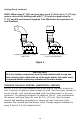
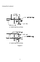
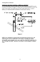
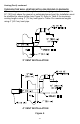
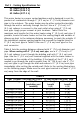
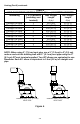
Table Of Contents

14
Venting (Part I) continued-
NOTE: When using 4” (10.2 cm) vent pipe, use a 4” (10.1 cm) to 3” (7.6 cm)
reducer and exit the building wall with 3” (7.6 cm) vent pipe using the
3” (7.6 cm) 90° vent terminal supplied. Two 45° elbows are equivalent to
one 90
° elbow.
CONNECTION TO A 3” (7.6 CM) TO
4” (10.2 CM) REDUCER
CONNECTION TO 3” (7.6 CM)
VENT PIPE
Figure 2
THROUGH THE WALL VENTING: (HORIZONTAL VENTING)
Cut a 3 1/2 in. (8.9 cm) diameter hole in the w all at the point where the
vent connector is going to pass through the wall. Use the proper cement to
secure the 90° vent terminal provided w ith the w ater heater to the vent
connector. The distance between the edges of the 90° vent terminal and
the exterior wall (see Figure 3) must be 1 in. (2.5 cm). Use the proper
cement and assembly procedures to secure the vent connector joints
between the terminal and the blower outlet. Provide support brackets for
every 5 feet (1.5 m) of horizontal vent.
IMPORTANT
All of the Venting connections must be leak checked with a soap and
water solution upon initial start up of the water heater. Any leaks must
be repaired before continuing operation of the water heater.