
Installation / Operation Instruction Manual
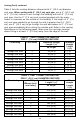
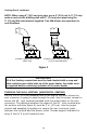
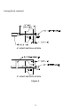
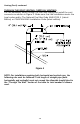
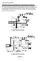
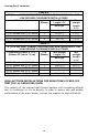
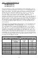
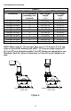
Table Of Contents

13
Venting (Part I) continued-
Table 2 lists the venting distances allowed with 4’’ (10.2 cm) diameter
vent pipe. When venting with 4’’ (10.2 cm) vent pipe, use a 4’’ (10.2 cm)
to 3’’ (7.6 cm) reducer to exit through the building wall with 3’’ (7.6 cm)
vent pipe. Use the 3’’ (7.6 cm) vent terminal supplied with the water
heater to terminate on the outside of the building. If the length of 3’’ (7.6
cm) vent pipe needed to go through the wall is greater than 14’’ (35.5
cm), use 4’’ (10.2 cm) to go through the wall and reduce to 3’’ (7.6 cm)
vent pipe immediately after exiting the outside w all. Refer to the venting
illustrations on the following pages. Make sure the vent pipe terminal
elbow fitting is at least 1’’ (2.5 cm) aw ay from the edge of the w all.
TABLE 1 - VENT CONNECTOR LENGTHS
FOR 3’’ (7.6 cm) DIAMETER VENT PIPE
Terminating
# of Elbows
Maximum straight
Length ft (m)
Minimum
straight
Length
ft (m)
48, 65 gal.
Through the Wall
1
55 (16.8)
2 (.6)
Through the Wall
2
50 (15.2)
2 (.6)
Through the Wall
3
45 (13.7)
2 (.6)
Through the Wall
4
40 (12.2)
2 (.6)
Through the Roof
0
60 (18.3)
7 (2.1)
Through the Roof
1
55 (16.8)
7 (2.1)
Through the Roof
2
50 (15.2)
7 (2.1)
Through the Roof
3
45 (13.7)
7 (2.1)
TABLE 2 -VENT CONNECTOR LENGTHS
FOR 4’’ (10.2 cm) DIAMETER VENT PIPE
Terminating
# of 90°
Elbows (excl.
vent term.)
Maximum straight
Length ft (m)
Min
straight
Length
ft (m)
48, 65 gal.
Through the Wall
1
175 (53.3)
10 (3.1)
Through the Wall
2
170 (51.8)
10 (3.1)
Through the Wall
3
165 (50.3)
10 (3.1)
Through the Wall
4
160 (48.8)
10 (3.1)
Through the Wall
5
155 (47.2)
10 (3.1)
Through the Roof
0
180 (54.9)
15 (4.6)
Through the Roof
1
175 (53.3)
15 (4.6)
Through the Roof
2
170 (51.8)
15 (4.6)
Through the Roof
3
165 (50.3)
15 (4.6)
Through the Roof
4
160 (48.8)
15 (4.6)