ELECTRIC WATER HEATER INSTALLATION & OPERATING INSTRUCTION MANUAL THE WARRANTY ON THIS WATER HEATER IS IN EFFECT ONLY WHEN THE WATER HEATER IS INSTALLED AND OPERATED IN ACCORDANCE WITH LOCAL CODES AND THESE INSTRUCTIONS. THE MANUFACTURER OF THIS HEATER WILL NOT BE LIABLE FOR ANY DAMAGE RESULTING FROM FAILURE TO COMPLY WITH THESE INSTRUCTIONS. READ THESE INSTRUCTIONS THOROUGHLY BEFORE STARTING.
TABLE OF CONTENTS General Information ..................................................... 3 Installation .................................................................... 4 Locating the Water Heater ..................................... 4 Technical Characteristics ...................................... 7 Water Connections ................................................. 8 Electrical Connections ............................................ 11 General Operation ..........................................
GENERAL INFORMATION This water heater must be installed in accordance with local codes. In the absence of local codes, install this water heater in accordance with the N.E.C. Reference Book (latest edition). The warranty for this water heater is in effect only when the water heater is installed, adjusted, and operated in accordance with these Installation and Operating Instructions.
General Information continued- IMPORTANT Before proceeding, please inspect the water heater and its components for possible damage. DO NOT install any damaged components. If damage is evident, please contact the supplier where the water heater was purchased, or the manufacturer listed on the rating plate for replacement parts.
Installation continued- DO NOT locate the water heater where water lines could be subjected to freezing temperatures. Locate the water heater so that access panels and drain valves are accessible. This water heater MUST be installed indoors. Failure to install this water heater indoors and protected from wind and weather will void the warranty. Water heater must be installed in vertical position with the water fittings pointing upward. Water heater must be positioned on the appropriate surface.
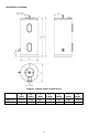
Installation continued- Figure 1: Water Heater Dimensions BW200-R BW300-R A (mm) 1201 1631 B (mm) 1165 1595 C (mm) 533 560 D (mm) 216 231 6 E (mm) 267 280 F (mm) 555 582 G (mm) 203 203
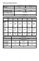
Technical Characteristics Type Capacity Water Pressure BW200-R 200 L 1MPa (10 bar) Net Weight (empty) Connections to the water supply network 26 kg 32 kg 3/4” NPT Temperature Range Phase Model Operation Nominal Power – Upper Heating Element (W) Nominal Power – Lower Heating Element (W) Nominal Voltage (VAC) BW300-R 300 L 32 to 66 °C Single (1PH) BW200R1NCPP BW200R1NCWW BW200R1NCZZ BW300R1NCPP BW300R1NCWW BW300R1NCZZ Non-simultaneous -/3000 3500/ 4500 4500/ 6000 -/3000 3500/ 4500 4500/ 600
Water Connections NOTE: BEFORE PROCEEDING WITH THE INSTALLATION, CLOSE THE MAIN WATER SUPPLY VALVE. After shutting the main water supply valve, open a faucet to relieve the water line pressure to prevent any water from leaking out of the pipes while making the water connections to the water heater. After the pressure has been relieved, close the faucet. The COLD-water inlet and HOT water outlet are identified on the water heater.
Water Connections continued- Your water supplier or local plumbing inspector should be contacted on how to control this situation. After installation of the water lines, open the main water supply valve and fill the water heater. While the water heater is filling, open several hot water faucets to allow air to escape from the water system. When a steady stream of water flows through the faucets, close them and check all water connections for possible leaks.
Water Connections continued- WARNING Hydrogen gas can be produced in a hot water system served by this water heater that has not been used for a long period of time (generally two weeks or more). Hydrogen gas is extremely flammable. To reduce the risk of injury under these conditions, it is recommended that the hot water faucet be opened for several minutes at the kitchen sink before using any electrical appliance connected to the hot water system.
Electrical Connections Before any electrical connections are made, be sure that the water heater is full of water and that the manual shut-off valve in the cold-water supply line is open. Check the rating plate and wiring diagram before proceeding. This electric water heater was built and wired in accordance with the IEC testing approvals requirements.
Electrical Connections continued- Figure 4A: 1 Phase, Non-Simultaneous Legend 1 2a 2b Connection box Upper thermostat with bipolar safety thermostat Lower thermostat 3a 3b 4a 4b L1 N Upper heating element Lower heating element Upper light indicator Lower light indicator Live Conductor Neutral Conductor WARNING WARNING! WATER HEATER EQUIPED FOR LIMITED RANGE OF VOLTAGE! This water heater is equipped for determinate range voltage 208/240 VAC or 415 VAC.
Electrical Connections continued- Figure 4B: 3 Phase, Simultaneous Legend 1 2a 2b 3a 3b 4a 4b L1 L2 L3 Connection box Upper thermostat with bipolar safety thermostat Lower thermostat with bipolar safety thermostat Upper heating element Lower heating element Upper light indicator Lower light indicator Live Conductor Live Conductor Live Conductor SAFETY SHUT-OFF Water heaters have a bipolar safety thermostat that works in case of abnormal heating of water.
GENERAL OPERATION Before closing the switch to allow electric current to flow to the water heater, make certain that the water heater is full of water and that the cold-water inlet valve is open. Complete failure of the heating element(s) will result if they are not totally immersed in water at all times. Failure of the element(s) due to dry-firing is not covered by warranty. When the switch is closed, the operation of this electric water heater is automatic.
Thermostat Adjustment Setting the Water Temperature 1. The thermostat has been set at the factory at about 52 °C to reduce the risk of scald injury. We recommend this setting as this ensures the most safe and economic operation of the water heater. This way the water temperature is maintained at about 52 °C. The operation of the heater at this temperature level also results in reduced build-up of calcium and lime, as well as reduced heat loss than is the case at higher temperatures. 2.
Thermostat Adjustment continued- LIGHT INDICATOR The operation of the heating element is indicated by the light indicator that stays on until the temperature in the tank has reached the set level or until the heater has been deliberately switched off. ANTIFREEZING PROTECTION When the water heater is not in use for longer periods of time, it should be protected from freezing by setting the temperature to minimum possible position. Do not disconnect the power.
MAINTENANCE IMPORTANT The water heater should be inspected at a minimum of annually by a qualified service technician for damaged components. DO NOT operate this water heater if any part is found damaged. Shut off the electric power whenever the water supply to the water heater is off. Shut off the electric power and water supply, drain the heater completely to prevent freezing whenever the building is left unoccupied during the cold weather months.
Maintenance continued- 3. At least once a year, check the combination temperature and pressure relief valve to ensure that the valve has not become encrusted with lime. Lift the lever at the top of the temperature-pressure relief valve several times until the valve seats properly without leaking and operates freely. WARNING When lifting lever of temperature-pressure relief valve, hot water will be released under pressure.
Maintenance continued- Draining the Water Heater 1. Unplug the water heater. 2. Open the hot tap to let hot water go out. Continue flowing until cold water is running out from faucet. 3. Turn off cold water supply. 4. Close the hot water faucet. 5. Connect suitable hose to draining valve to prevent uncontrolled spilling. 6. Open draining valve to drain the water.
NOTES 20