
Installation / Operation Instruction Manual


Page 34
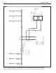
This unit’s eciency is higher with lower return
water temperatures. Therefore, to get the most of low
return temperature with multiple boilers, pipe as shown in
Figure 22 through Figure 28
All boiler models can be ordered with a pump. When
the pump is included with the boiler, the boiler must be
located within 15 feet (4.6m) of the supply/return header
(or hydraulic separator). These units must be piped in
a primary-secondary fashion, such that the pump that
is included only serves the boiler. The pumps are sized
for the headloss of the boiler and a maximum of 30 feet
(9.1m) of piping that is the same size as the boiler water
connections See Table 15.
If longer pipe lengths or alternate piping methods are
being used, the pump must be sized for the boiler
and the piping it will serve. Table 13 on page 32
shows water ow and headloss data for the boiler. The
manufacturer strongly recommends primary-secondary
piping.
6.A.2 Boiler Cold Water Make-Up
1. Connect the cold water supply to the inlet
connection of an automatic ll valve.
2. Install a suitable back ow preventer between the
automatic ll valve and the cold water supply.
3. Install shut o valves where required.
The boiler piping system of a hot water heating boiler
connected to heating coils located in air handling
appliances where they may be exposed to refrigerated
air circulation must be equipped with ow control valves
or other automatic means to prevent gravity circulation
of the boiler water during the cooling cycle.
A boiler installed above radiation level, or as required by
the authority having jurisdiction, must be provided with a
low water cuto device either as a part of the boiler or at
the time of boiler installation.
6.A.3 Condensate Drain
A condensate drain trap is built into the unit.
No additional or secondary trap is required. .
BOILER PIPE SIZE, HEATER PIPE SIZE,
SIZE INCHES SIZE INCHES
- - 150 1¼
- - 199 1¼
- - 285 2
399 1¼ 399 2
500 1½ 500 2
600 1½ 600 2
750 2 750 2
850 2 850 2
Table 15. Water Connection Pipe Sizes
SECTION 6
WATER CONNECTIONS - Part A
Section 6 is divided into two parts. Section
6A covers Boiler units designed for hydronic
heating. Section 6B covers Heater models,
which are designed exclusively for “volume
water” domestic hot water applications. Refer
to the proper section for instructions on
installing and piping your product. Refer to
Table 9 for the connection pipe sizes required.
6.A Boiler
6.A.1 Boiler Water Piping -
NOTE: This appliance must be installed in a closed
pressure system with a minimum of 12 psi (82.7kPa)
static pressure at the boiler.
Water piping should be supported by suitable hangers or
oor stands. Do not support piping with this appliance.
Due to expansion and contraction of copper pipe,
consideration should be given to the type of hangers
used. Rigid hangers may transmit noise through the
system resulting from the piping sliding in the hangers.
It is recommended that padding be used when rigid
hangers are installed. Maintain 1” (2.5cm) clearance to
combustibles for hot water pipes.
Pipe the discharge of the relief valve (full size) to a drain
or in a manner to prevent injury in the event of pressure
relief. Install an air purger, an air vent, a diaphragm-type
expansion tank, and a hydronic ow check in the system
supply loop. Minimum ll pressure must be 12psig
(82.7kPa). Install shuto valves where required by code.
B
RADFORD
W
HITE