
Installation / Operation Instruction Manual


Page 28
Bradford White Corp
SECTION 6 Operating Instructions
6.A Filling the Boiler System
1. Ensure the system is fully connected. Close all
bleeding devices and open make-up water valve.
Allow system to ll slowly.
2. If make-up water pump is employed, adjust
pressure switch on pumping system to provide
a minimum of 12 psi (81.8 kPa) at the highest
point in the heating loop.
3. If a water pressure regulator is provided on the
make-up water line, adjust the pressure regulator
to provide at least 12 psi (81.8 kPa) at the highest
point in the heating loop.
4. Open bleeding devices on all radiation units
at the high points in the piping throughout
the system, unless automatic air bleeders are
provided at such points.
5. Run system circulating pump for a minimum of
30 minutes with the boiler shut o.
6. Open all strainers in the circulating system,
check ow switch operation, and check for
debris. If debris is present, clean out to ensure
proper circulation.
7. Recheck all air bleeders as described in Step 4.
8. Check liquid level in expansion tank. With the
system full of water and under normal operating
pressure, the level of water in the expansion tank
should not exceed ¼ of the total, with the balance
lled with air.
9. Start up boiler according to the procedure in this
manual. Operate the entire system, including the
pump, boiler, and radiation units for one (1) hour.
10. Recheck the water level in the expansion tank. If
the water level exceeds ¼ of the volume of the
expansion tank, open the tank drain, and drain to
that level.
11. Shut down the entire system and vent all
radiation units and high points in the system
piping, as described in Step 4.
12. Close make-up water valve and check strainer in
pressure reducing valve for sediment or debris
from the make-up water line. Reopen make-up
water valve.
13. Check gauge for correct water pressure and also
check water level in the system. If the height
indicated above the boiler insures that water is at
the highest point in the circulating loop, then the
system is ready for operation.
14. Refer to local codes and the make-up water
valve manufacturer’s instructions as to whether
the make-up water valve should be left open or
closed.
15. After placing the unit in operation, the ignition
system safety shuto device must be tested.
First, shut o the manual gas valve, and call
the unit for heat. After the pre-purge and ignitor
heat-up time, the main gas terminals will be
energized, attempting to light, for seven (7)
seconds, and then will de-energize. The unit will
attempt to light two more times, and then will go
into lockout mode. Second, turn the power o
and then on again, open the manual gas valve
and allow the unit to light. While the unit is
operating, close the manual gas valve and ensure
that power to the main gas valve has been cut.
16. Within three (3) days of start-up, recheck all air
bleeders and the expansion tank as described in
Steps 4 and 8 above.
Important: The installer is responsible for identifying
to the owner/operator the location of all emergency
shutoff devices.
WARNING
Do not use this appliance if any part has been under
water. Immediately call a qualified service technician
to inspect the appliance and to replace any part of
the control system and any gas control that may have
been under water.
AVERTISSEMENT
N’utilisez pas cet appareil si l’une de ses pièces est
passée sous l’eau. Appelez tout de suite un technicien
en entretien et en réparation pour inspection de
l’appareil et remplacement des pièces du système de
commande, et des pièces de commande du circuit
gaz, qui sont passées sous l’eau.
6.B Operating Temperature Control
(Note: BMT2 can be ordered with either an on/o or
2-stage controller.)
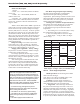
6.B.1 Operating Temperature Control
on Hydronic Boilers
Summary of Dip Switch Settings:
#1 Two Stage (O) / Single Stage (On)
#2 Setpoint (O) / Outdoor Reset (On) (Note:
Outdoor Reset is required for residential
operation)
#3 WWSD Inactive (O) / Active 70°F (On)
#4 Boiler Maximum 210°F (O) / 190°F (On)
#5 Pump Post Purge Inactive (O) / Active 3
min. (On)
40
41
42
48
51
43
44
45
46
47
49
50
52
53
54
54
55
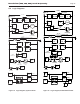
The Control
Access Panel