
Installation / Operation Instruction Manual


Page 17
Brute Deluxe (200, 300, 400), Install & Operating
Model
(Size)
20°F 25°F 30°F 35°F
flow
gpm
H/L
feet
flow
gpm
H/L
feet
flow
gpm
H/L
feet
flow
gpm
H/L
feet
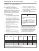
200 17 1.6 14 1.0 11 0.7 10 0.5
300 26 3.5 20 2.3 17 1.6 15 1.2
400 34 6.3 27 4.0 23 2.8 19 2.1
Metric Equivalent
Model
(Size)
11°C 14°C 17°C 19°C
ow
lpm
H/L
m
ow
lpm
H/L
m
ow
lpm
H/L
m
ow
lpm
H/L
m
200 64 0.5 51 0.3 43 0.2 37 0.2
300 97 1.1 77 0.7 64 0.5 55 0.4
400 129 1.9 103 1.2 86 0.9 74 0.6
Notes: gpm = gallons per minute, lpm = liters per minute,
H/L = head loss, ft = head loss in feet,
m = head loss in meters.
Maximum temperature rise is 35°F (19°C), as shown.
Head loss is for boiler’s heat exchanger only.
N/R = not recommended.
Table 7. Water Flow Requirements - BMT2H.
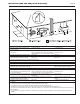
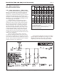
Figure 5. Hydronic Piping — Multiple Boilers, Primary Secondary System.
4.B Water Connections —
Brute Deluxe Water Heater
4.B.1 Water System Piping — Water Heater
Hot water piping should be supported by suitable
hangers or oor stands. Do not support piping with
this appliance. Due to expansion and contraction of
copper pipe, consideration should be given to the type
of hangers used. Rigid hangers may transmit noise
through the system resulting from the piping sliding in
the hangers. It is recommended that padding be used
when rigid hangers are installed.
The Brute Deluxe can be used with several
dierent types of readily available storage tanks. A
pump draws water from the storage tank and pumps
the water through the heater and back into the tank.
Pump-mounted units have a circulating pump built
into the water heater. The pumps used are sized for
the head loss through the heater, plus 30 feet (9.1 m)
of full-sized piping (same size as boiler outlet) and
a normal number of ttings. Pumps used on pump-
mounted unit are sized for soft/normal or hard water,
so make sure a pump-mounted unit matches the water
quality of the installation.
Pipe the outlet from the heater’s relief valve
such that any discharge from the relief valve will be
conducted to a suitable place for disposal when relief
occurs. Do not reduce line size or install any valves in
this line. The line must be installed to allow complete
drainage of both the valve and the line.
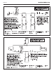
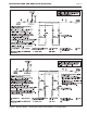
Suggested piping diagrams are shown as Figure 5,
Figure 6, Figure 7, and Figure 8, and Figure 9. These
diagrams are meant only as a guide. Components
required by local codes must be properly installed.