Installation and Operation Instructions Document 1244C Installation and Operation Instructions for Hydronic Boiler Model BMT2H Water Heater Model BMT2V Sizes 200, 300, 400 FOR YOUR SAFETY: This product must be installed and serviced by a professional service technician, qualified in hot water boiler installation and maintenance. Improper installation and/or operation could create carbon monoxide gas in flue gases which could cause serious injury, property damage, or death.
Page 2 Bradford White Corp TABLE OF CONTENTS SECTION 1. General Information 1.1 1.2 1.3 1.4 1.5 1.6 1.7 1.8 Introduction....................................................... 3 Model Identification........................................... 4 Warranty........................................................... 4 Dimensions....................................................... 4 Locating the Appliance.....................................
Brute Deluxe (200, 300, 400), Install & Operating Page 3 SECTION 1. General Information USING THIS MANUAL – Because the Brute Deluxe Boilers and Brute Deluxe Water Heaters are identical appliances, with the exception of materials of manufacture, labels and ultimate use application, this manual provides information for the proper installation, operation and maintenance of both products.
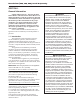
Page 4 1 Bradford White Corp 2 3 4 B M T 2 B M SERIES T 5 6 7 9 10 11 12 13 C SIZE USAGE 2 8 14 15 16 2 FUEL LOCATION H 0 2 0 0 N C V 0 3 0 0 P 0 4 0 0 FIRING MODE REVISION C 2 K HEAT EXCHANGER OPTIONS CODE B X X C L N N P PUMP OPTIONS S G 2 5 1.2 Model Identification Consult the rating plate on the unit. The following information describes the model number structure.
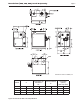
Brute Deluxe (200, 300, 400), Install & Operating Page 5 Dimensions shown in inches, cm. Model 200 300 400 A in. 20.5 26.5 33.6 cm 52 67 85 Combustion Air Connection B* in. cm 4 10 4 10 6 15 Vent Connection C* in. 5 6 7 cm 13 15 18 *Air and vent connections may be on top or back of the Brute Deluxe, and are field convertible. Figure 1A. Dimensional Data - Non Pump Mounted. Horizontal (Cat III) Vent Pipe Size in.
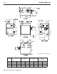
Page 6 Bradford White Corp Dimensions shown in inches, cm. Model 200 300 400 A in. 20.5 26.5 33.6 cm 52 67 85 Combustion Air Connection B* in. cm 4 10 4 10 6 15 Vent Connection C* in. 5 6 7 cm 13 15 18 *Air and vent connections may be on top or back of the Brute Deluxe, and are field convertible. Figure 1b. Dimensional Data - Pump Mounted. Horizontal (Cat III) Vent Pipe Size in.
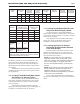
Brute Deluxe (200, 300, 400), Install & Operating Page 7 Vent Collar Size Horizontal Vent Pipe Diameter Intake Air Collar & Pipe Diameter Max. Pipe Length in cm in cm in cm ft m 200 5 13 4 10 4 10 50 300 6 15 5 13 4 10 400 7 18 6 15 6 15 Heater Size Max. No. of Elbows Side Vent Terminal Part Number Side Wall Combustion Air Terminal Part Number 15 3 CA003101 CA003201 50 15 3 CA003102 CA003201 50 15 3 CA003103 CA003202 Table 1.
Page 8 SECTION 2. Venting and Combustion Air WARNING For indoor installations, as an additional measure of safety, National Combustion Co. strongly recommends installation of suitable Carbon Monoxide detectors in the vicinity of this appliance and in any adjacent occupied spaces. AVERTISSEMENT Pour des installations intérieures, National Combustion Co.
Brute Deluxe (200, 300, 400), Install & Operating Table 3. Combustion Air Openings. 2.1.2 Intake Combustion Air The combustion air can be taken through the wall, or through the roof. When taken from the wall, it must be taken from out-of-doors by means of the Bradford White horizontal wall terminal (see Table 1). When taken from the roof, a field-supplied rain cap or an elbow arrangement must be used to prevent entry of rain water (see Figure 2).
Page 10 WARNING Operation of appliances with a blocked common vent may lead to serious injury or death. Safety devices must be implemented to prevent blocked common vent operation. If safe operation of all appliances connected to a common vent cannot be assured, including prevention of spillage of flue gasses into living spaces, common venting should not be applied, and appliances should each be vented separately.
Brute Deluxe (200, 300, 400), Install & Operating Page 11 U.S. Installations (see note 1) Canadian Installations (see note 2) A= Clearance above grade, veranda, porch, 12 inches (30 cm) 12 inches (30 cm) deck, or balcony B= Clearance to window or door that may Direct Vent Only: 12 inches (30 cm) be opened Other Than Direct Vent: 4 feet (1.
Page 12 4. 5. 6. Bradford White Corp gravity inlets or other openings. Whenever possible, locations under windows or near doors should be avoided. Locate the vent terminal so that it cannot be blocked by snow. The installer may determine that a vent terminal must be higher than the minimum shown in codes, depending upon local conditions. Locate the terminal so the vent exhaust does not settle on building surfaces or other nearby objects. Vent products may damage such surfaces or objects.
Brute Deluxe (200, 300, 400), Install & Operating 2. (c) Product Approved side wall horizontal vented gas fueled equipment installed in a room or structure separate from the dwelling, building or structure used in whole or in part for residential purposes. MANUFACTURER REQUIREMENTS – GAS EQUIPMENT VENTING SYSTEM PROVIDED.
Page 14 4. 5. 6. 7. common venting system are located and other spaces of the building. Turn on clothes dryers and any appliance not connected to the common venting system. Turn on any exhaust fans, such as range hoods and bathroom exhausts, so they will operate at maximum speed. Do not operate a summer exhaust fan. Close fireplace dampers. Place in operation the appliance being inspected. Follow the lighting instructions. Adjust thermostat so appliance will operate continuously.
Brute Deluxe (200, 300, 400), Install & Operating Page 15 3. 4. Refer to Table 7, size supply. Run gas supply line in accordance with all applicable codes. 5. Locate and install manual shutoff valves in accordance with state and local requirements. 6. A sediment trap must be provided upstream of the gas controls. 7. All threaded joints should be coated with piping compound resistant to action of liquefied petroleum gas. 8.
Page 16 WARNING Do not use open flame to check for leaks. An open flame could lead to explosion, which could result in property damage, serious injury or death. AVERTISSEMENT Ne recherchez pas les fuites avec une flamme nue. Une flamme nue peut provoquer une explosion qui peut causer des dommages matériels, de sérieuses blessures corporelles ou la mort.
Brute Deluxe (200, 300, 400), Install & Operating water flow requirements by 15%, and increase the head loss requirements by 20%. Power outage, interruption of gas supply, failure of system components, activation of safety devices, etc., may prevent a boiler from firing. Any time a boiler is subjected to freezing conditions, and the boiler is not able to fire, and/or the water is not able to circulate, there is a risk of freezing in the boiler or in the pipes in the system. When water freezes, it expands.
Page 18 Figure 5. Hydronic Piping — Multiple Boilers, Low Temperature System. Figure 6. Hydronic Piping — One Boiler, Multi-Temperature System.
Brute Deluxe (200, 300, 400), Install & Operating Figure 7. Hydronic Piping — Primary-Secondary, Reverse-Return. Figure 8. Hydronic Piping — Primary-Secondary, Reverse-Return, Low Temperature.
Page 20 ethylene glycol (automotive antifreeze). SECTION 4B. Water Connections — Brute Deluxe Water Heater 4B.1 Water System Piping — Water Heater Hot water piping should be supported by suitable hangers or floor stands. Do not support piping with this appliance. Due to expansion and contraction of copper pipe, consideration should be given to the type of hangers used. Rigid hangers may transmit noise through the system resulting from the piping sliding in the hangers.
Brute Deluxe (200, 300, 400), Install & Operating Page 21 or component(s) previously used with a non-potable water heating appliance. When the system requires water for heating at temperatures higher than required for other uses, an anti-scald mixing or tempering valve shall be installed to temper the water for those uses in order to reduce scald hazard potential. 4B.
Page 22 Bradford White Corp KEY: WATER CATEGORY GRAIN HARDNESS PER GALLON 1 THROUGH 7.5 S = SOFT N = NORMAL 7.6 THROUGH 17 OVER 17 H = HARD PPM / 17.1 = Grains Per Gallon 1 SU PP LY CAUTION: THIS DRAWING SHOWS SUGGESTED PIPING CONFIGURATION AND VALVING, CHECK WITH LOCAL CODES AND ORDINANCES FOR ADDITIONAL REQUIREMENTS. 2 NOTES: 1. OPTIONAL CWMU & RECIRC. LINE LOCATION. 2. LOCATE PENNANT DHW SENSOR OR REMOTE AQUASTAT WELL IN LOWER 1/3 OF TANK. 3 4 CW MU 3. BACK FLOW PREVENTER MAY BE REQUIRED.
Brute Deluxe (200, 300, 400), Install & Operating Page 23 CAUTION: THIS DRAWING SHOWS SUGGESTED PIPING CONFIGURATION AND VALVING, CHECK WITH LOCAL CODES AND ORDINANCES FOR ADDITIONAL REQUIREMENTS. KEY: WATER CATEGORY GRAIN HARDNESS PER GALLON 1 THROUGH 7.5 S = SOFT N = NORMAL 7.6 THROUGH 17 OVER 17 H = HARD PPM / 17.1 = Grains Per Gallon 4 3 MU CW 1 C. R CI RE 2 LY PP SU 2 NOTES: 1. OPTIONAL CWMU & RECIRC. LINE LOCATION. 2.
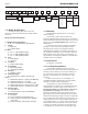
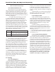
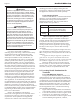
IGN IGN 240 120 BK F1 F2 Y 24V BL/R L1 L2 IGN/FS IGNITOR W W BK BK FIELD INTERLOCK BL/R BL/R R STAGE 1 GAS VALVE PRESSURE SWITCH AIR BOX/BURNER C NO FLOW SWITCH R BR/BK G TH PSW VAL GND E0253400 FUSE F1 BK TRANSFORMER 115 VAC INPUT 115V 24 VAC OUTPUT 24 FC +VAC BK BK BL/R G R/W W W BK GY/BK L2 GY/BK BK V/W W GY/V POWER 2 1 P2 Y/BLK 6V + - STAGE 2 GAS VALVE OPTIONAL LWCO Y Y R/BK 6V + - Y BL BL/R Y Y Y R/BK R ST.
Brute Deluxe (200, 300, 400), Install & Operating Page 25 SECTION 5. Electrical Connections Single pole switches, including those of safety controls and protective devices must not be wired in a POWER grounded line.
Page 26 SECTION 6. Operating Instructions 6.1 Filling the Boiler System 1. 2. 3. 4. 5. 6. 7. 8. 9. 10. 11. 12. 13. 14. 15. Ensure the system is fully connected. Close all bleeding devices and open make-up water valve. Allow system to fill slowly. If make-up water pump is employed, adjust pressure switch on pumping system to provide a minimum of 12 psi (81.8 kPa) at the highest point in the heating loop.
Brute Deluxe (200, 300, 400), Install & Operating LEDs State Description 1. Power 2. Heat – On = call for heat; Flashes for Boiler sensor error 3. DHW – On = call for DHW; Flashes for outdoor sensor error 4. WWSD – On = Outdoor Reset AND WWSD Active AND control in WWSD; Flashes for outdoor sensor error, operation continues with fixed boiler target of 140°F. When a call for HEAT and/or DHW is present the pump contact (5A max) will be energized.
Page 28 differential/2. 2. Target Max - The boiler target maximum is the point at which the stages will start to turn off to maintain a maximum water temperature. The Boiler Maximum water temperature is set by setting dip switch #4: Boiler Maximum 210°F (Off) / 190°F (On).
Brute Deluxe (200, 300, 400), Install & Operating 6.6 Operating the Burner and Set-Up 6.6.1 Set-Up for 0 to 2500 Feet Altitude The setup must be checked before the unit is put in operation. Problems such as failure to start, rough ignition, strong exhaust odors, etc. can be due to improper setup. Damage to the Brute Deluxe resulting from improper setup is not covered by the limited warranty. 1. 2. 3. 4. 5. 6. 7. 8. 9.
Page 30 6.7 Shutting Down the Brute Deluxe 1. 2. 3. Switch off the main electrical disconnect switch. Close all manual gas valves. If freezing is anticipated, drain the Brute Deluxe and be sure to also protect building piping from freezing. This step to be performed by a qualified service person. 6.8 To Restart the Brute Deluxe Bradford White Corp 4. 5. If drained, follow Section 6.1 in this manual for proper filling and purging. 6. 1. 2. 3. 4. 7. 5. 6. 7. 8.
Brute Deluxe (200, 300, 400), Install & Operating g. h. i. j. k. l. High limit Pump (if required) Relays Flow switch Gas train Control components 7.2.1 Burners Close main manual gas valve before proceeding. Checking the burners for debris - Remove the ignitor/ burner access panel and ignitor, and inspect the burners through the ignitor hole using a flashlight to illuminate. If there is any indication of debris on the burners that is visible, all the burners will need to be inspected more thoroughly.
Page 32 allowed. To replace the flow switch, turn off the 120volt power to the appliance. Isolate the boiler or water heater from the system by closing the isolation valves. Caution Water may be hot enough to scald. Allow water to cool before proceeding. Attention L’eau peut être chaude au point de vous brûler. Laissez refroidir l’eau avant d’intervenir. Release pressure in the system by actuating the pressure relief valves or field supplied boiler drain valve.
Brute Deluxe (200, 300, 400), Install & Operating SECTION 8. Trouble Shooting 8.1 Resolving Lockouts There are many causes of lockouts. The three most common causes are: (1) inadequate gas supply, (2) poor combustion, (3) ignitor failure. 1. 2. 3. Inadequate gas supply: Before proceeding, ensure that the gas supply has not been shutoff or the LP tank (LP boilers) is not empty. Then, restart the boiler and observe the operational cycle.
Page 34 Bradford White Corp SECTION 9. Replacement Parts Only genuine Bradford White replacement parts should be used. 9.1 General Information To order or purchase parts for the Bradford White Brute Deluxe, contact your nearest Bradford White dealer or distributor. If they cannot supply you with what you need, contact Customer Service (see back cover for address, telephone and fax numbers). 9.
Brute Deluxe (200, 300, 400), Install & Operating Item Description Page 35 Model 200 Model 300 Model 400 JACKET COMPONENTS See Figure 21 40 Panel, Front, Jacket R2C3320 R3C3320 R4C3320 41 Panel, Rear, Jacket 2C3220 3C3220 4C3220 42 Panel, Top, Jacket 2C3021 3C3021 4C3021 43 Panel, Jacket, Control Access 2F3019 3F3019 4F3019 44 Panel, HX Side Access, Jacket 2C3620 2C3620 2C3620 45 Panel, Right Side, Upper, Jacket 2C3621 2C3621 2C3621 46 Panel, Right Side, Jacket 2C3520
Page 36 Item Bradford White Corp Description Model 200 Model 300 Model 400 GAS TRAIN COMPONENTS See Figure 23 80 Weldment, Gas Manifold, Main L0063702 L0063703 L0063704 81 Manifold, Gas, On/Off L0063414 L0063416 L0063418 82 Manifold, Gas, 2 Stage Left Bank L0063404 L0063413 L0063414 83 Manifold, Gas, 2 Stage Right Bank L0063402 L0063403 L0063405 84 Orifice, Nat.
Brute Deluxe (200, 300, 400), Install & Operating Page 37 21 19 20 31 16 22 17 31 19 31 32 18 23 24 30 31 8 6 12 13 5 4 9 11 26 28 27 7 14 25 15 10 29 3 2 31 Figure 20. Combustion Chamber Components.
Page 38 Bradford White Corp 51 52 50 42 49 48 43 41 45 47 44 46 53 40 55 54 54 Figure 21. Jacket Components.
Brute Deluxe (200, 300, 400), Install & Operating Page 39 71 65 68 70 69A 66 67 61 63 64 63 72 73 64 62 69B 60 Figure 22. Heat Exchanger Components.
Page 40 Bradford White Corp 80 87 86 ON/OFF 81 84 85 80 86 2 STAGE 86 82 84 85 Figure 23. Gas Train Components.
Brute Deluxe (200, 300, 400), Install & Operating Page 41 104 102 106 97 Figure 24. Control Panel Components.
Page 42 Bradford White Corp H2357900C Dimensions and specifications subject to change without notice in accordance with our policy of continuous product improvement. 200 Lafayette St. Middleville, MI 49333 Warranty: (800) 531-2111 www.BradfordWhite.com Litho in U.S.A.