
Installation / Operation Instruction Manual


BLP SERIES Install, Operation, and Maintenance Manual
SECTION 4: MAINTENANCE
Rev-1 Bradford White • 200 Lafayette St. • Middleville, MI 49333 Page 56 of 83
BrutePlate Manual Phone: (800) 531-2111 • Website: www.BradfordWhite.com 02/26/2020
initiate operation of the unit.
12. Unit should be checked for leaks and correct pressure levels to ensure proper operation.
4.4 T&P OR PRESSURE ONLY RELIEF VALVE REPLACEMENT
If the water pressure or T&P relief valve mounted on the unit is not functioning correctly and
must be replaced, follow the procedures outlined below.
T&P RELIEF VALVE REPLACEMENT INSTRUCTIONS
1) Before performing this maintenance procedure, follow the shutdown procedure in Section
3.8 to take the unit offline.
WARNING!
TURN OFF/DISCONNECT ALL ELECTRIC POWER BEFORE ATTEMPTING ANY
MAINTENANCE PROCEDURE.
2) Carefully disconnect the drain line from the relief valve to the drain.
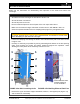
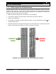
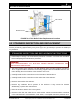
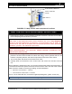
3) Unscrew and remove the T&P relief valve from its mounting location (Fig. 4-4).
4) Install the new relief valve in place. Tighten until sealed and facing proper orientation for
reconnection to the drain line.
NOTE: Use and type of joint sealer should be determined from local codes or the
specifications of the installing contractor. Reconnect the drain line from the relief valve to
the drain per local codes.
5) If any were disconnected, reconnect all electric and pneumatic lines, and restore power
and instrument air to the system.
6) Reference the manufacturer’s documentation for the T &P relief valve that was
supplied with your unit for additional installation/setup instructions.
7) Follow the startup procedures to put the unit back online. Carefully check all connections
for any sign of leakage.